Optical system for collecting distance information within a field

an optical system and distance information technology, applied in optics, condensers, instruments, etc., can solve the problems of much less power of vcsels than the laser less efficient spads than detectors used in velodyne architecture, etc., to achieve small footprint, sufficient reliability, and cheap manufacturing.

Active Publication Date: 2018-06-14
OUSTER INC
View PDF0 Cites 56 Cited by
  • Summary
  • Abstract
  • Description
  • Claims
  • Application Information

AI Technical Summary

Benefits of technology

[0015]Embodiments of the invention pertain to a LIDAR sensor that can, among other uses, be used for obstacle detection and avoidance in autonomous vehicles. Some specific embodiments pertain to LIDAR sensors that include design features that enable the sensors to be manufactured cheaply enough and with sufficient reliability and to have a small enough footprint to be adopted for use in mass-market automobiles, trucks and other vehicles. For example, some embodiments include a set of vertical-cavity surface-emitting lasers (VCSELs) as illumination sources that emit radiation into a field and include arrays of single-photon avalanche diode (SPAD) detectors as a set of pixels (detectors) that detect radiation reflected back from a surface in the field. Using VCSELs as the emitters and SPADs as the detectors enables multiple measurements to be taken at the same time (i.e., the VCSEL emitters can be fired simultaneously) and also enables the set of emitters and the set of pixels to each be fabricated using standard CMOS processes on a single chip, greatly simplifying the manufacturing and assembly process.

Problems solved by technology

For example, VCSELs are much less powerful than the lasers used in the Velodyne architecture and SPADs are much less efficient than the detectors used in the Velodyne architecture.

Method used


Image

  • Optical system for collecting distance information within a field
  • Optical system for collecting distance information within a field
  • Optical system for collecting distance information within a field

Examples


Embodiment Construction

[0032]The following description of embodiments of the invention is not intended to limit the invention to these embodiments but rather to enable a person skilled in the art to make and use this invention. Variations, configurations, implementations, example implementations, and examples described herein are optional and are not exclusive to the variations, configurations, implementations, example implementations, and examples they describe. The invention described herein can include any and all permutations of these variations, configurations, implementations, example implementations, and examples.

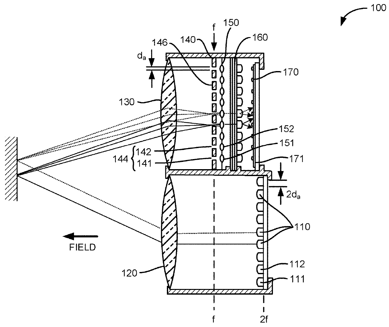
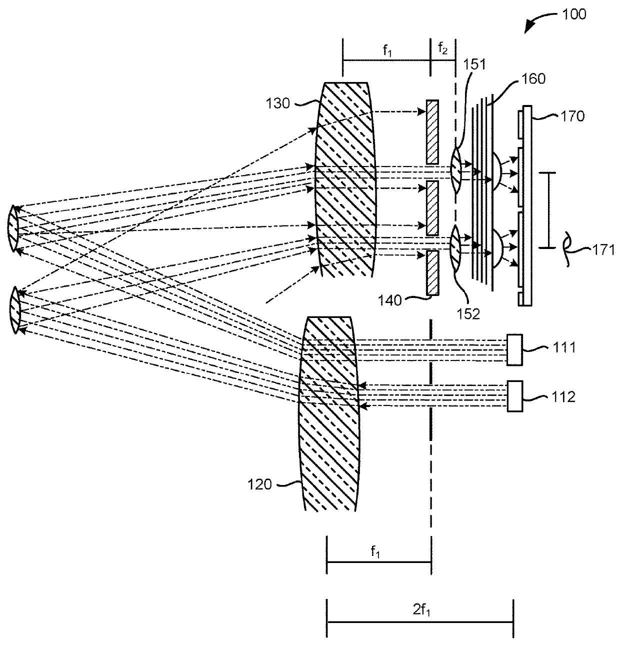
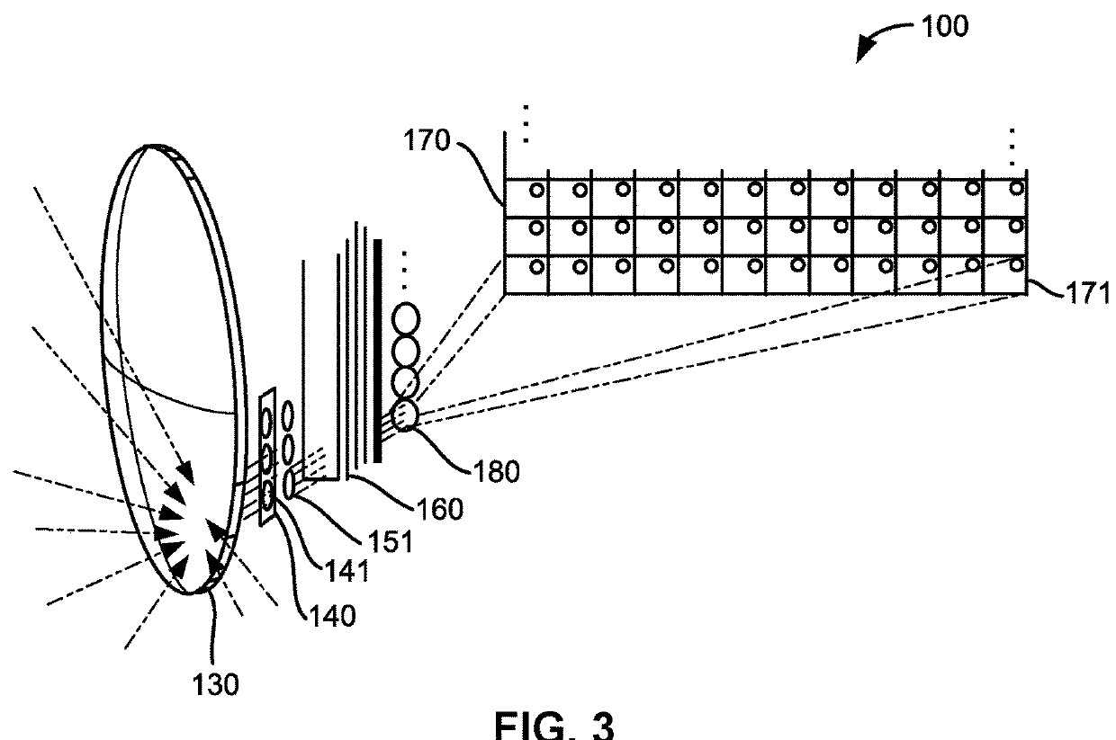
[0033]1. One-Dimensional Optical System: Aperture Array

[0034]As shown in FIG. 1, a one-dimensional optical system 100 for collecting distance information within a field includes: a set of illumination sources 110 arranged along a first axis, each illumination source in the set of illumination sources 110 configured to output an illuminating beam of an operating wavelength toward a discrete...


PUM


Abstract

An optical system for collecting distance information within a field is provided. The optical system may include lenses for collecting photons from a field and may include lenses for distributing photons to a field. The optical system may include lenses that collimate photons passed by an aperture, optical filters that reject normally incident light outside of the operating wavelength, and pixels that detect incident photons. The optical system may further include illumination sources that output photons at an operating wavelength.

Description

CROSS-REFERENCE TO RELATED APPLICATIONS[0001]This application is a continuation-in-part of U.S. Nonprovisional patent application Ser. No. 15 / 276,532, filed on Sep. 26, 2016, which claims the benefit of U.S. Provisional Patent Application No. 62 / 232,222 filed Sep. 24, 2015. The disclosures of each of the '532 and '222 above-referenced applications are hereby incorporated by reference in their entirety for all purposes.FIELD OF THE INVENTION[0002]This invention relates generally to the field of optical sensors and more specifically to a new and useful optical system for collecting distance information in the field of optical sensors.BACKGROUND OF THE INVENTION[0003]Light imaging, detection and ranging (LIDAR) systems measure distance to a target by illuminating the target with a pulsed laser light and measuring the reflected pulses with a sensor. Time-of-flight measurements can then be used to make a digital 3D-representation of the target. LIDAR systems can be used for a variety of ...

Claims


Application Information

Patent Timeline
Patent Type & Authority Applications(United States)
IPC IPC(8): G02B27/42G02B3/00G02B5/20G02B5/00G02B27/22
CPCH04N13/218G02B5/208G02B5/005G02B3/0056G02B27/42G02B27/2214G02B5/28G02B19/0066G02B30/27H04N13/395
Inventor PACALA, ANGUSFRICHTL, MARK
Owner OUSTER INC
Why Eureka
Try Eureka