Automatically opening tool with sliding scale release

a technology of sliding scale and automatic opening, which is applied in the direction of metal working apparatus, etc., can solve the problems of inconvenient user service or reconfiguration, not easily serviced by users, and not easily reconfigured for both left-hand and right-hand activation. , to achieve the effect of convenient service or reconfiguration by users

Active Publication Date: 2018-06-21
HALUCHA WALTER +1
View PDF22 Cites 11 Cited by
  • Summary
  • Abstract
  • Description
  • Claims
  • Application Information

AI Technical Summary

Benefits of technology

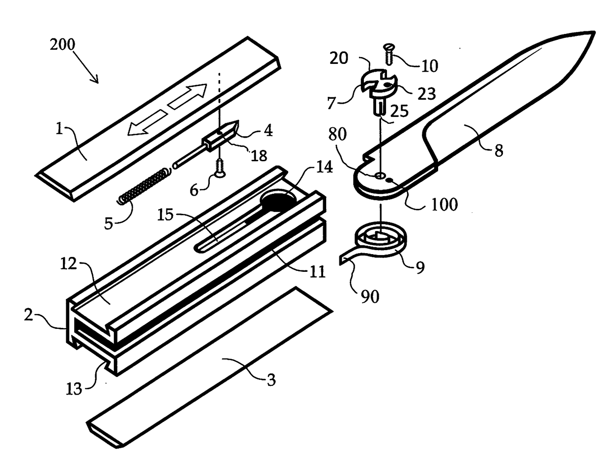
[0007]An automatically opening tool with a sliding scale release according to the present disclosure can be configured for both right-hand and left-hand use. It has fewer parts and is easily serviced or reconfigured by a user. Tools in accordance with the invention can have a sliding scale th

Problems solved by technology

Typically, they are not internally user serviceable, and are not readily reconfigurable for both left-hand and right-hand activation. FIG. 5a shows a Flylock with the scale installed. FIG. 5b shows a Flylock with the scale removed.
This makes them inconvenient for users to service or reconfigue.
The resulting tolerance fit leave

Method used


Image

  • Automatically opening tool with sliding scale release
  • Automatically opening tool with sliding scale release
  • Automatically opening tool with sliding scale release

Examples


Embodiment Construction

[0034]The present disclosure may be understood more readily by reference to the following detailed description of the disclosure taken in connection with the accompanying drawing figures, which form a part of this disclosure. It is to be understood that this disclosure is not limited to the specific devices, methods, conditions or parameters described and / or shown herein, and that the terminology used herein is for the purpose of describing particular embodiments by way of example only and is not intended to be limiting of the claimed disclosure.

[0035]Also, as used in the specification and including the appended claims, the singular forms “a,”“an,” and “the” include the plural, and reference to a particular numerical value includes at least that particular value, unless the context clearly dictates otherwise. Ranges may be expressed herein as from “about” or “approximately” one particular value and / or to “about” or “approximately” another particular value. When such a range is expre...


PUM


Abstract

An automatic opening tool with sliding scale release, including a modular body; a tool; a gear assembly attachable to the tool; a first resilient member for rotating the tool; a sear configured to mate with the gear assembly; a second resilient member for imparting a resilient force to the sear; and cover plates.

Description

CROSS REFERENCE TO RELATED APPLICATIONS[0001]This application claims priority to provisional application Ser. No. 62 / 436,570, filed Dec. 20, 2016, the entire contents of which are incorporated herein by reference.BACKGROUND[0002]The invention relates generally to spring-activated tools, such as knives, which can be opened automatically with the activation of a release.[0003]Automatic knives and other tools with spring loaded blades have a variety of configurations and release button designs. For example, some knives have a reciprocating (sliding) button and are referred to as having Flylock mechanisms. Existing Flylock sliding buttons generally move along the long longitudinal axis of the knife, within a cavity in the front, distal portion of the handle. As used herein, for purposes of reference only, an open knife will be referred to as oriented with its tip at its distal end and its blade edge facing upwards, to define a front left side of the handle and a rear right side of the h...

Claims


Application Information

Patent Timeline
IPC IPC(8): B26B1/04
CPCB26B1/042B26B1/048B26B1/04
Inventor HALUCHA, WALTER
Owner HALUCHA WALTER
Why Eureka
Try Eureka