System and method for automatically inspecting surfaces

a technology of automatic inspection and large objects, applied in the direction of process and machine control, vehicle position/course/altitude control, instruments, etc., can solve the problems of large objects, detection and locating defects, and general hard-to-reach surfaces, and achieve the effect of quick inspection of large surfaces

Active Publication Date: 2018-06-21
DONECLE
View PDF2 Cites 36 Cited by
  • Summary
  • Abstract
  • Description
  • Claims
  • Application Information

AI Technical Summary

Benefits of technology

[0024]An automatic inspection system according to the invention therefore allows for an inspection, via one or more flying robots (commonly called drones or unmanned aerial vehicles); the inspection system therefore significantly reduces the number of human operators required, as each flying robot of the fleet inspects one portion of the surface of the object to be inspected. The quantity of equipment required is thus reduced, in addition to the safety risks for the operators.
[0066]According to this aspect of the invention, a result is transmitted immediately after each processing operation, thus allowing the information on the presence of potential defects to be progressively obtained over time, without waiting for the inspection to be completed. The transmission is carried out as soon as possible, i.e. by taking into account the different processing times and the availability of a transmission channel allocated to the transmission if said channel is shared between a plurality of flying robots.

Problems solved by technology

Large objects, i.e. objects whose dimensions, bulk and / or weight do not allow them to be carried by a person, generally have hard-to-reach surfaces, for example portions of buildings or engineering structures that are situated at height, the outer hull of large ships, the structure of an oil platform or the upper part of train sections or aircraft fuselages and wings.
Detecting and locating defects visible to the eye on this type of large object therefore presents several problems, in particular problems concerning obtaining visual access to the surfaces, detecting defects and locating defects in a coordinate system related to the object.
However, these inspections performed by one or more human operators have several drawbacks.
The installation of specific equipment such as scaffolding in order to obtain visual access to the surfaces is time-consuming and expensive, and does not systematically provide easy access to the surfaces to be inspected.
The use of binoculars or equivalent optical means in order to overcome this drawback is unsatisfactory as this reduces the efficiency of the inspection.
Moreover, the use of specific equipment generally increases safety risks for the operator, in particular falling or crushing risks, or any other risk brought about by the use of specific equipment such as cherry pickers or scaffolding.
The specific equipment also generates risks for the object, in particular collision risks capable of causing deterioration.
Depending on the fragility of the object, this deterioration could have significant repercussions, such as immobilisation or grounding (for vehicles and aircraft), expensive repairs or the permanent suspension of operation.
These drawbacks and risks are all the more important as the number of operators increases.
Furthermore, the detection performed by the operators is imperfect, as an operator could forget to visually scan a portion of the surface, in particular if the surface is hard to reach.
Finally, the subjectivity of each operator can result in a different classification of the elements perceived (for example between major defects, minor defects, normal wear or marks), which could lead the operator to ignore or only belatedly detect certain defects.
Moreover, the operators must be specially trained for the inspection, which reduces the number of operators capable of performing the inspection and requires additional management with regard to the availability and cost of a team of trained operators.
Finally, the locating techniques can produce errors, in particular with regard to the selection and identification of the points of reference, for example if this selection requires a high number of repetitive elements to be counted (portholes, windows, columns, etc.), which can be added to the conventional errors made when measuring from one or more points of reference.
The inspections performed with the existing systems and methods are also subjected to an additional speed problem.
Current inspections generally require the operation of the object to be suspended over a long period of time.
In order to improve inspection speed, the number of operators responsible for conducting this inspection must be increased, which in particular generates additional costs and increases the risks described hereinabove.
However, the problem of acquiring visual access remains and the method is slow, insofar as an operator is required to intervene for each detection.
This system however cannot be used for buildings and engineering structures, cannot be displaced and is not modular.
In particular, such a system requires the object to be inspected, for example an aircraft, to be transported to the hangar, which is expensive and complex.

Method used


Image

  • System and method for automatically inspecting surfaces
  • System and method for automatically inspecting surfaces
  • System and method for automatically inspecting surfaces

Examples


Embodiment Construction

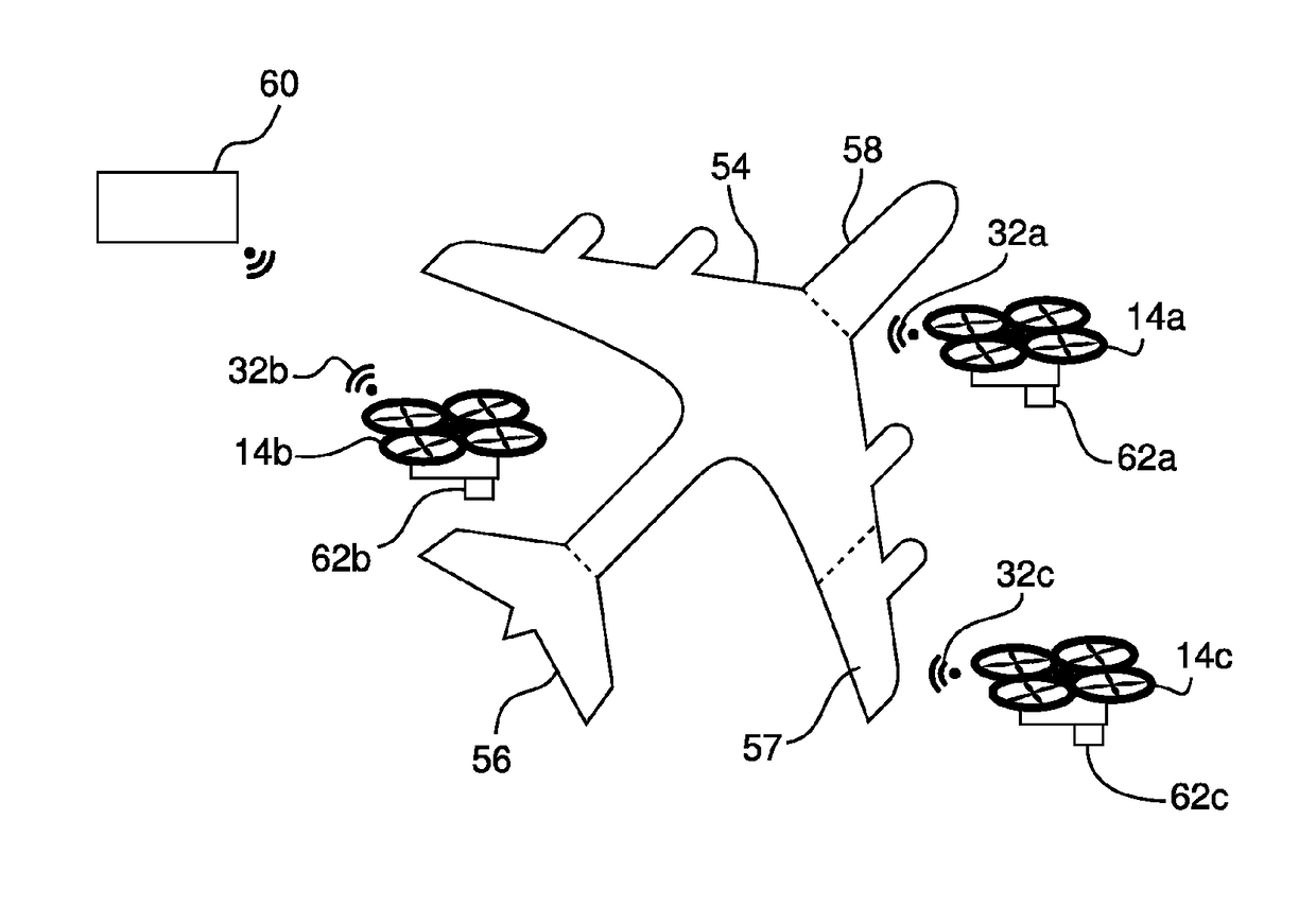
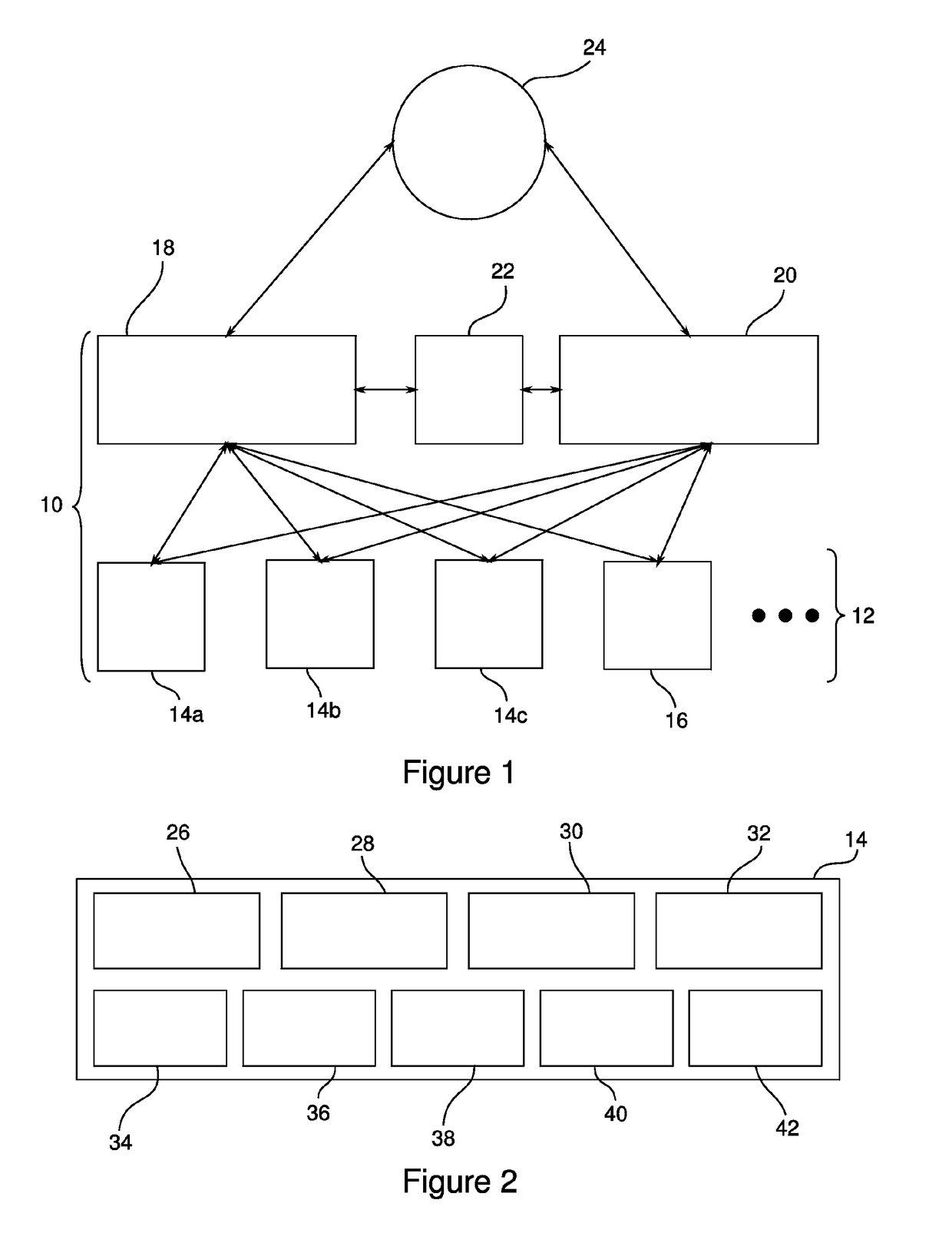
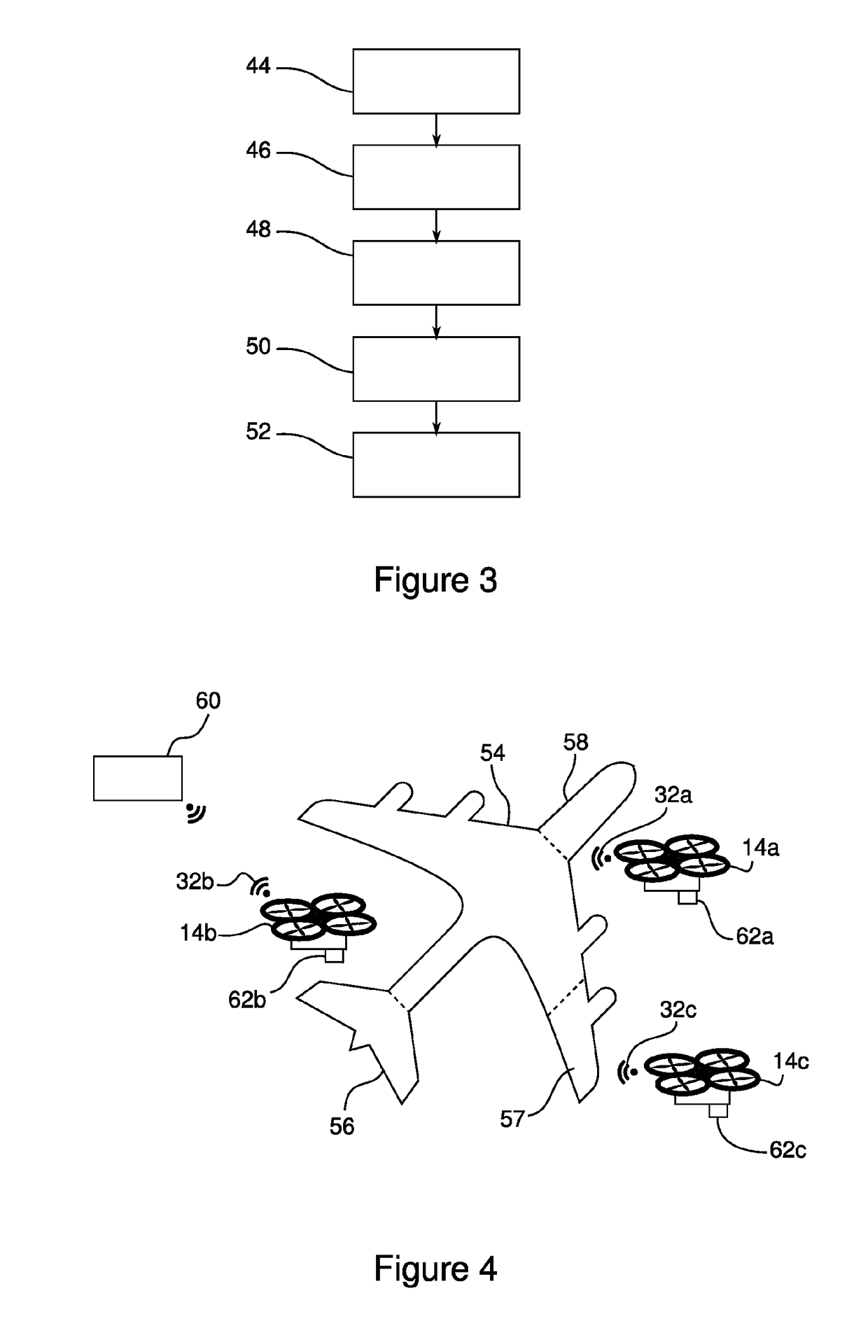
[0020]For this purpose, the invention relates to a system for automatically inspecting a surface of an object such as an aircraft, transport vehicle, building or engineering structure, said surface being liable to contain a defect, characterised in that it comprises a fleet, comprising at least one flying robot, each flying robot comprising:

[0021]a module for acquiring images of at least one portion of the surface to be inspected, and

[0022]a module for processing the acquired images, which module is suitable for providing information representative of the state of each inspected surface portion, which information is called the processing result,

[0023]the automatic inspection system further comprising a module for managing the fleet of robots, the management module being suitable for determining, from a model of the surface to be inspected, a set of displacement instructions and image acquisition instructions for each robot of the fleet.

[0024]An automatic inspection system according ...


PUM


Abstract

The invention relates to a system for automatically inspecting a surface of an object such as an aircraft (54), a transport vehicle, a building or an engineering structure, said surface being liable to contain a defect.The system is characterised in that it comprises a fleet comprising at least one flying robot (14a, 14b, 14c), each flying robot comprising a module for acquiring images of at least one portion of the surface to be inspected, and a module for processing the acquired images, which module is suitable for providing information representative of the state of each inspected surface portion, which information is called the processing result.

Description

TECHNICAL FIELD OF THE INVENTION[0001]The invention relates to a system and a method for automatically inspecting large-scale objects. In particular, the invention relates to the detection and locating of defects on hard-to-reach surfaces of said large-scale objects.TECHNOLOGICAL BACKGROUND[0002]The technical field of the invention concerns the detection and locating of defects visible to the human eye over large surfaces, such as the outer surfaces of large objects, for example aircraft, ships, trains, motor vehicles, buildings or engineering structures. In general, the term “object” shall be understood herein as a tangible thing that can be perceived through sight and touch, made by man and intended for a specific use. Large objects, i.e. objects whose dimensions, bulk and / or weight do not allow them to be carried by a person, generally have hard-to-reach surfaces, for example portions of buildings or engineering structures that are situated at height, the outer hull of large ship...

Claims


Application Information

Patent Timeline
Patent Type & Authority Applications(United States)
IPC IPC(8): B64C39/02B64F5/60G05D1/00G05D1/10
CPCB64C39/024B64F5/60G05D1/0094G05D1/104B64C2201/123B64C2201/143B64U2101/30B64U2201/102B64U2101/00
Inventor CLAYBROUGH, MATTHIEU
Owner DONECLE
Why Eureka
Try Eureka