Liquid discharging apparatus and circuit substrate

a technology of liquid discharging apparatus and circuit substrate, which is applied in the direction of electrical apparatus, piezoelectric/electrostrictive/magnetostrictive devices, printing, etc., can solve problems such as signal degradation

Active Publication Date: 2018-06-28
SEIKO EPSON CORP
View PDF3 Cites 22 Cited by
  • Summary
  • Abstract
  • Description
  • Claims
  • Application Information

AI Technical Summary

Benefits of technology

[0004]An advantage of some aspects of the invention is to provide a liquid discharging apparatus that can reduce a possibility that signal degradation occurs due to interference of a drive signal and a control signal with each other in a circuit substrate and that can accurately discharge a liquid. Another advantage of some aspects of the invention is to provide a circuit substrate that can reduce a possibility that signal degradation occurs due to interference of a drive signal and a control signal with each other.
[0023]In the liquid discharging apparatus according to the application example, in the circuit substrate, a difference between the wiring impedance of the first drive signal transmitting wiring and the wiring impedance of the second drive signal transmitting wiring is small since the width of the first drive signal transmitting wiring that is longer than the second drive signal transmitting wiring is larger than the width of the second drive signal transmitting wiring. Therefore, in the liquid discharging apparatus according to the application example, a difference between the accuracy of discharging the first liquid and the accuracy of discharging the second liquid can be reduced since a difference between the accuracy of transmitting the first drive signal and the accuracy of transmitting the second drive signal can be reduced in the circuit substrate.
[0030]In the circuit substrate according to the application example, the first drive signal transmitting wiring and the first control signal transmitting wiring are separated away from each other since the first drive signal transmitting wiring is provided next to the first side and the first control signal transmitting wiring is provided next to the second side opposing the first side. Therefore, in the circuit substrate according to the application example, a possibility that at least one of the first drive signal and the first control signal degrades due to interference of the first drive signal propagated by the first drive signal transmitting wiring and the first control signal propagated by the first control signal transmitting wiring with each other can be reduced. Thus, the first liquid can be accurately discharged by the connected head unit.

Problems solved by technology

In a circuit substrate where wiring which transmits the signals are formed, there is a possibility that signal degradation occurs when transmitting the signals due to interference of the drive signal and the control signal with each other depending on the layout of the wiring.

Method used


Image

  • Liquid discharging apparatus and circuit substrate
  • Liquid discharging apparatus and circuit substrate
  • Liquid discharging apparatus and circuit substrate

Examples


modification example

10. Modification Example

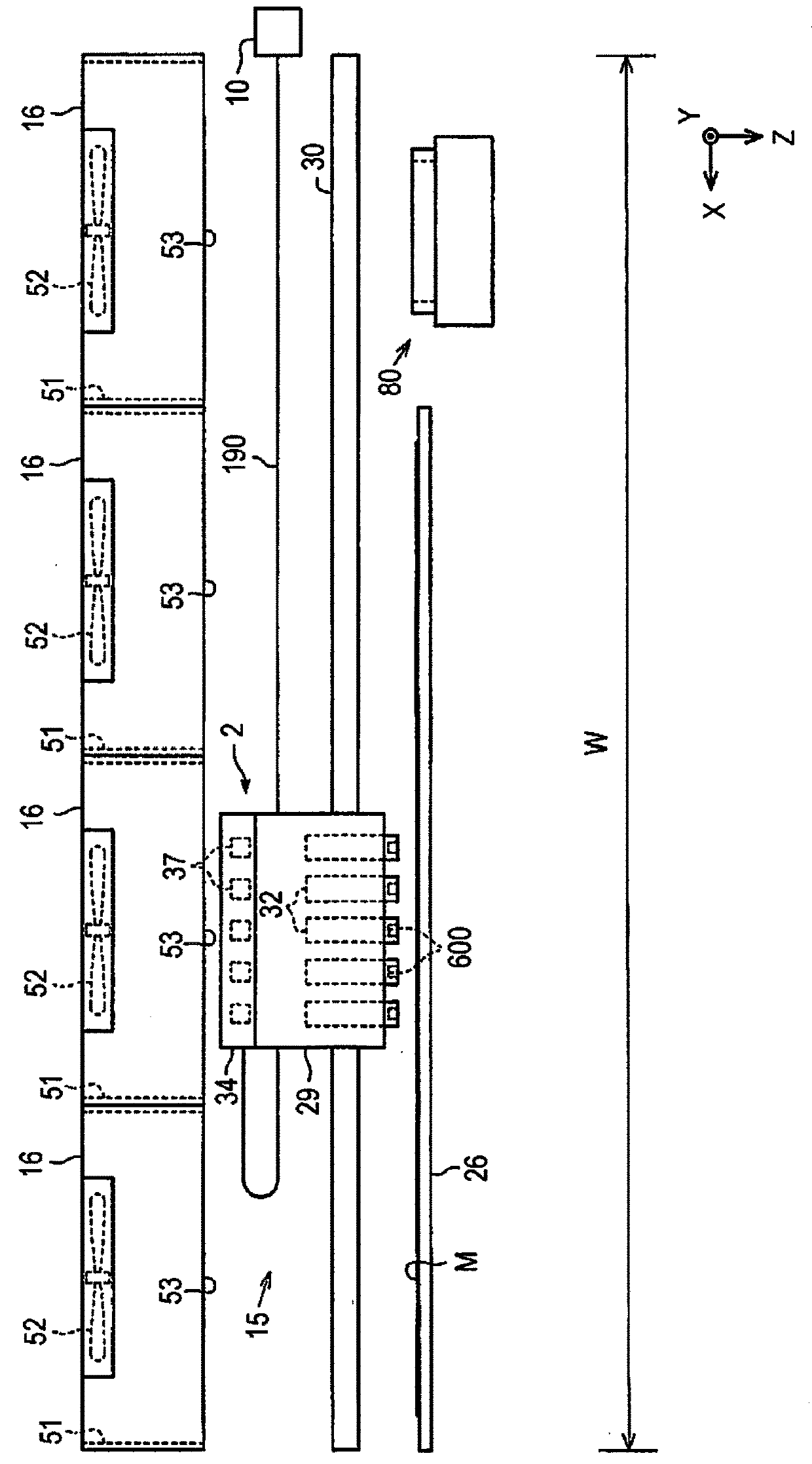
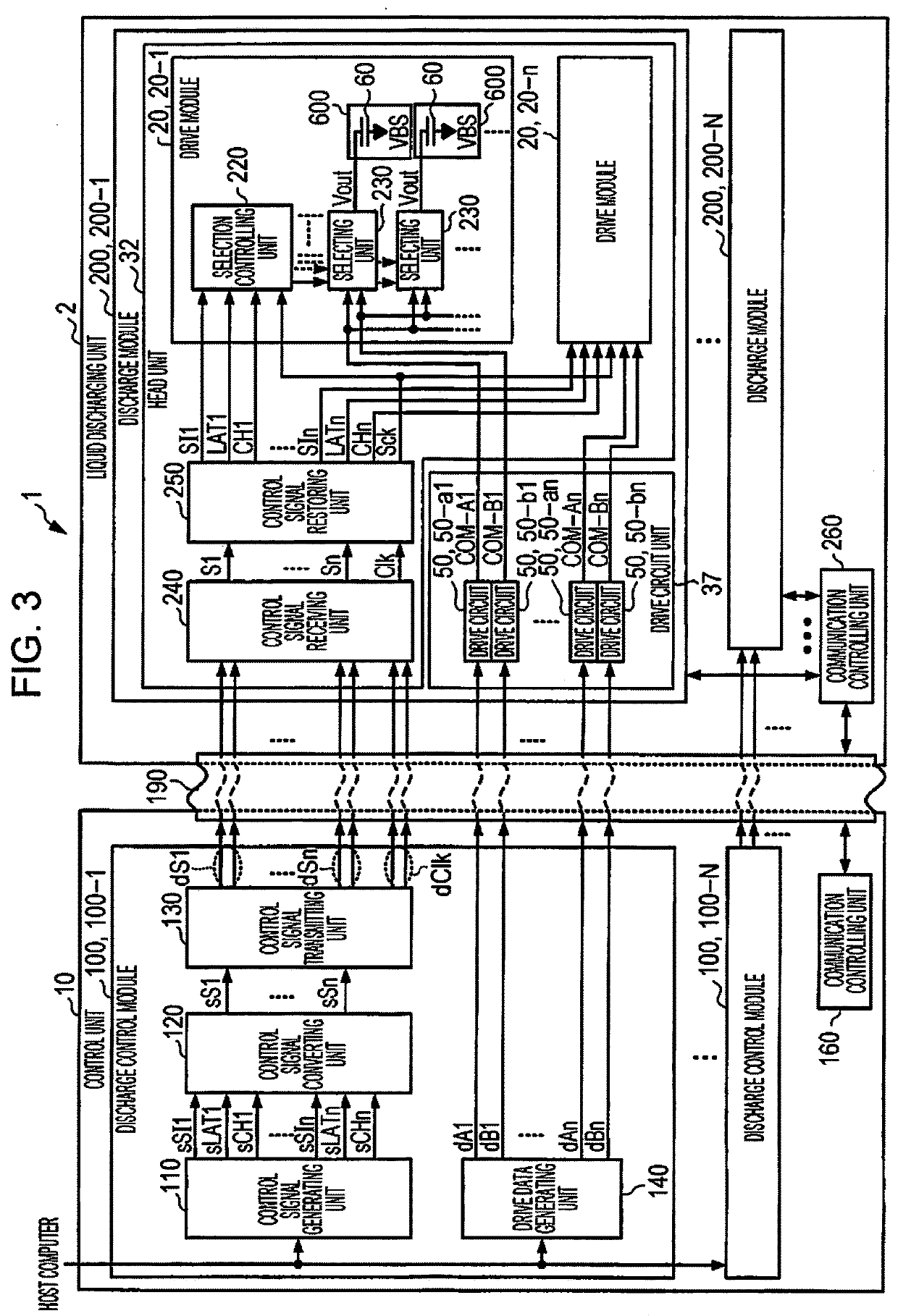
[0230]Although the control unit 10 and the liquid discharging unit 2 are connected to each other by at least one flexible flat cable 190 in the embodiment described above, the control unit and the liquid discharging unit may be connected to each other by a plurality of flexible flat cables. For example, each of the N flexible flat cables may transmit the drive data pieces dA1 to dAn and dB1 to dBn, the differential signals dS1 to dSn, and the differential clock signal dClk to each of the discharge modules 200. Although various types of signals are transmitted from the control unit 10 to the liquid discharging unit 2 by the (wired) flexible flat cable 190 in embodiment described above, the signals may be wirelessly transmitted.

[0231]Although a piezoelectric liquid discharging apparatus, in which a drive circuit drives a piezoelectric element (capacitive load) as a driving element, is given as an example in the embodiment described above, the invention is also ...


PUM


Abstract

There is provided a liquid discharging apparatus including a head unit that has a first driving element and discharges a first liquid based on a first drive signal for driving the first driving element and a first control signal for controlling application of the first drive signal to the first driving element and a circuit substrate. First drive signal transmitting wiring through which the first drive signal is transmitted. The shortest distance between a first side of the circuit substrate and the first drive signal transmitting wiring is shorter than the shortest distance between the first drive signal transmitting wiring and the first control signal transmitting wiring. The shortest distance between a second side opposing the first side of the circuit substrate and the first control signal transmitting wiring is shorter than the shortest distance between the first drive signal transmitting wiring and the first control signal transmitting wiring.

Description

BACKGROUND1. Technical Field[0001]The present invention relates to a liquid discharging apparatus and a circuit substrate.2. Related Art[0002]An apparatus using a piezoelectric element is known as a liquid discharging apparatus such as an ink jet printer that discharges inks and prints an image or characters. The piezoelectric element is provided so as to correspond to each of a plurality of discharging units in a head (ink jet head), and each of the discharging units is driven in accordance with a drive signal. As a consequence, a predetermined amount of an ink (liquid) is discharged at predetermined timing from nozzles of the discharging units, forming dots. In JP-A-2014-188914, a relay substrate in which wiring to transmit a signal for driving a head to a discharge head is disclosed.[0003]The signal for driving a head includes a drive signal to drive the piezoelectric element provided so as to correspond to each nozzle and a control signal to control application of the drive sign...

Claims


Application Information

Patent Timeline
Patent Type & Authority Applications(United States)
IPC IPC(8): B41J2/045B41J2/14H01L41/047
CPCB41J2/04541B41J2/14088B41J2/14233H01L41/0477B41J2/0458B41J2/04581B41J2/04588B41J2/04593B41J2/04596B41J2002/14491B41J2/17556B41J29/377B41J29/393H10N30/877
Inventor NAKAJIMA, AKIRA
Owner SEIKO EPSON CORP
Why Eureka
Try Eureka