Vehicle lamp

a technology for lamps and vehicles, applied in the field of lamps for vehicles, can solve the problems of increasing costs inevitably, and achieve the effect of effectively suppressing the large sagging portion

Inactive Publication Date: 2018-07-05
KOITO MFG CO LTD
View PDF12 Cites 6 Cited by
  • Summary
  • Abstract
  • Description
  • Claims
  • Application Information

AI Technical Summary

Benefits of technology

[0034]When the distance in the vehicle width direction is large, the light distribution pattern, which is to be formed by the simultaneous lighting of the plurality of light-emitting elements, has large sagging portions at both end portions thereof in the right and left direction if the plurality of light-emitting elements is arranged on the same line extending in in the vehicle width direction, like the related art. However, the above configuration is adopted, so that it is possible to effectively suppress the large sagging portion from being formed.
[0035]The vehicle lamp may be configured so that a distance in a front and back direction of a vehicle between a light-emitting center of a light-emitting element, which is located at the most distant position from the focus in the vehicle width direction, of the plurality of light-emitting elements and the focus is one-tenth or longer of the distance in the vehicle width direction between the light-emitting center and the focus. According to this configuration, it is possible to more effectively suppress the large sagging portion from being formed at both end portions in the right and left direction of the light distribution pattern, which is to be formed by the simultaneous lighting of the plurality of light-emitting elements.
[0036]The vehicle lamp may be configured so that at least one of the plurality of light-emitting elements can be selectively turned on and off. According to this configuration, it is possible to form a plurality of types of shapes of light distribution patterns, in addition to the light distribution pattern, which is to be formed by the simultaneous lighting of all the plurality of light-emitting elements. In this case, when the light-emitting elements to be selectively turned on and off are appropriately combined, it is possible to widely illuminate a forward traveling road without causing a glare to a driver of an oncoming vehicle or a forward traveling vehicle.

Problems solved by technology

Therefore, a configuration of a lighting control circuit for forming the plurality of types of light distribution patterns is complicated and it is necessary to detect a breaking or a short for each of the numerous wiring channels, so that the cost inevitably increases.

Method used


Image

  • Vehicle lamp
  • Vehicle lamp
  • Vehicle lamp

Examples


first modified embodiment

[0130]First, the illustrative embodiment is described.

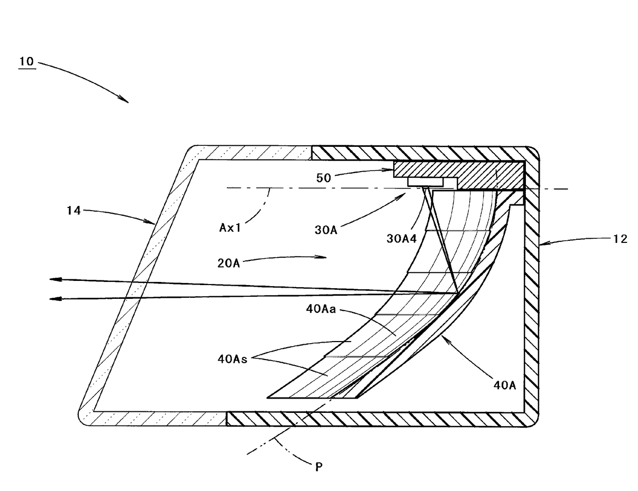
[0131]FIG. 10 is a view similar to FIG. 3, depicting a vehicle lamp 110 in accordance with the first modified embodiment.

[0132]Although the basic configuration of the vehicle lamp 110 is similar to the vehicle lamp 10 of the first illustrative embodiment, a direction of a light source unit 30A of a lamp unit 120A thereof is different.

[0133]That is, in the first modified embodiment, the light-emitting element 30A4 and the like configuring the light source unit 30A of the lamp unit 120A are arranged with the light-emitting surfaces thereof facing obliquely downward toward the rear. Accompanied by this, the shapes of the support member 150, the lamp body 112 and the translucent cover 114 are different from the first illustrative embodiment.

[0134]By adopting the configuration of the first modified embodiment, it is possible to enable the more emission light from the light-emitting element 30A4 and the like to reach the reflective sur...

second modified embodiment

[0136]Subsequently, the first illustrative embodiment is described.

[0137]FIG. 11 is a view similar to FIG. 4, depicting a main part of a vehicle lamp in accordance with the second modified embodiment.

[0138]Although the basic configuration of the second modified embodiment is similar to the first illustrative embodiment, a configuration of a light source unit 230B of a lamp unit 220B and a configuration of the four wiring channels ch1 to ch4 are different from the first illustrative embodiment.

[0139]In the second modified embodiment, the light source unit 230B has three light-emitting elements 230B1, 230B2, 230B3.

[0140]A configuration and an arrangement of the two light-emitting elements 230B1, 230B2 of the three light-emitting elements 230B1, 230B2, 230B3 are similar to the two light-emitting elements 30B1, 30B2 configuring the light source unit 30B of the first illustrative embodiment, and the remaining one light-emitting element 230B3 is located at a position slightly distant left...

third modified embodiment

[0150]Subsequently, the first illustrative embodiment is described.

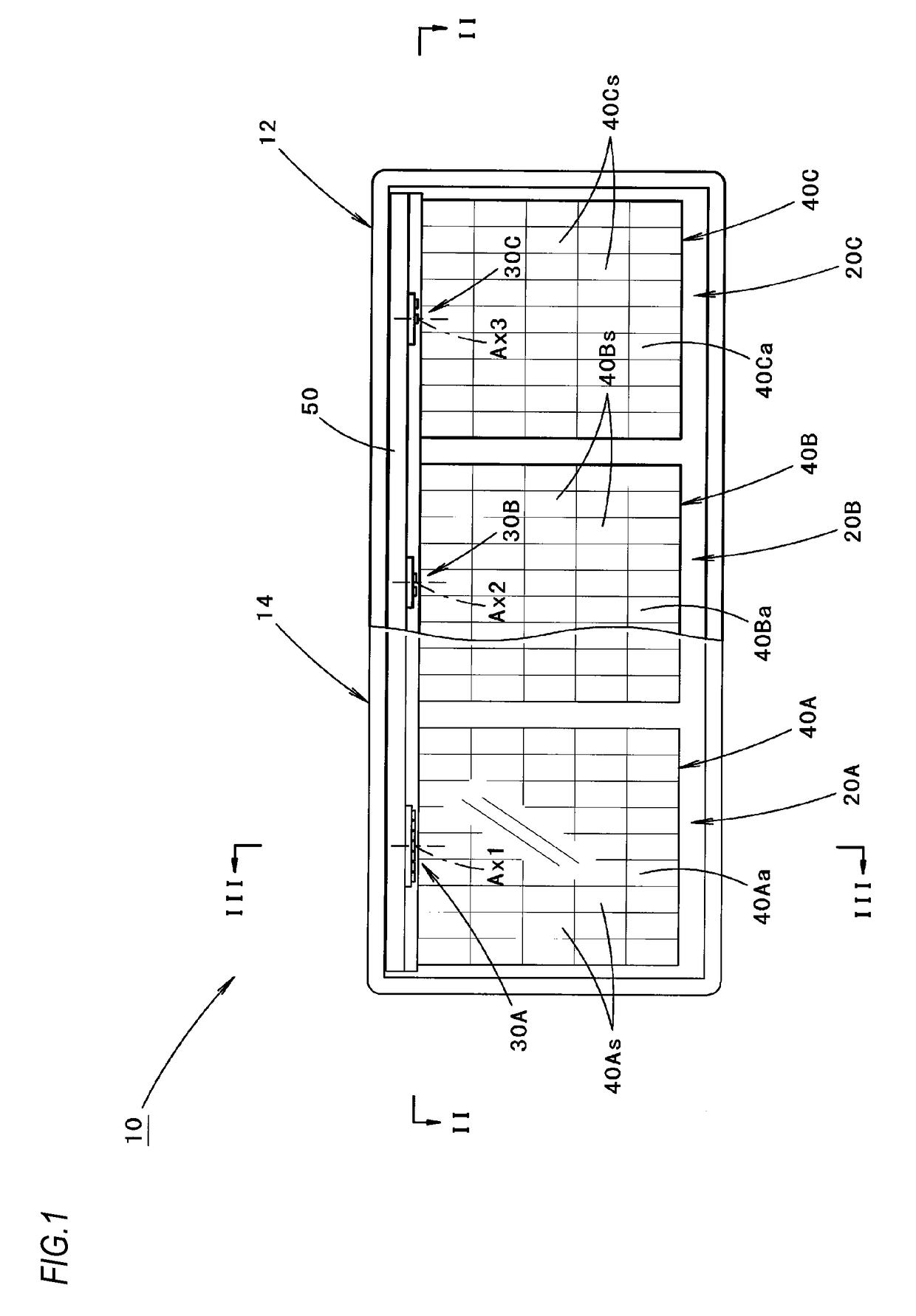
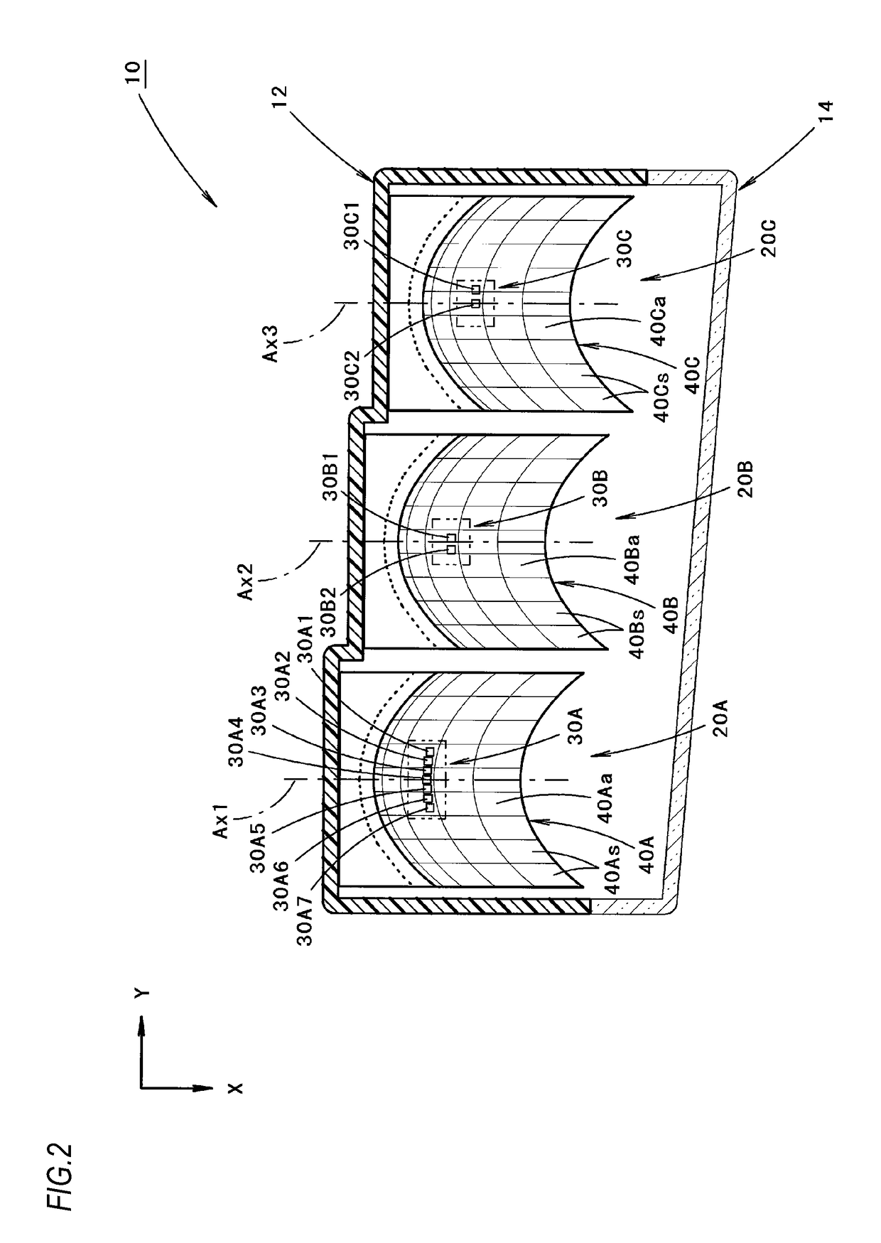
[0151]FIG. 13 is a view similar to FIG. 2, depicting a vehicle lamp 310 in accordance with the third modified embodiment.

[0152]As shown in FIG. 13, although the basic configuration of the vehicle lamp 310 is similar to the vehicle lamp 10 of the first illustrative embodiment, it is different from the first illustrative embodiment, in that a lamp unit 320C is arranged instead of the lamp unit 20C of the first illustrative embodiment.

[0153]In the third modified embodiment, the lamp unit 320C is configured as a projector-type lamp unit, not the reflector unit.

[0154]The lamp unit 320C includes a projector lens 322 having an optical axis Ax4 extending in the front and back direction of the vehicle, and a light source unit 330C arranged at the rear of the projector lens 322, and is configured to illuminate forward the emission light from the light source unit 330C via the projector lens 322.

[0155]The projector lens 322 is ...


PUM


Abstract

A first lamp unit includes a plurality of first light-emitting elements arranged in a vehicle width direction. A second lamp unit includes a plurality of second light-emitting elements arranged in the vehicle width direction. A wiring channel of a first type lights at least one of the first light-emitting elements by supplying power thereto, thereby forming a light distribution pattern of a first type. A wiring channel of a second type connects at least one of the first light-emitting elements in series with at least one of the second light-emitting elements, and lights these by supplying power thereto, thereby forming a light distribution pattern of a second type. The position of a light-dark boundary that extends vertically in the light distribution pattern of the first type is different from the position of a light-dark boundary that extends vertically in the light distribution pattern of the second type.

Description

CROSS-REFERENCE TO RELATED APPLICATIONS[0001]The present application claims foreign priority to Japanese Patent Application No. 2015-129567 filed on Jun. 29, 2015, and Japanese Patent Application No. 2015-129826 filed on Jun. 29, 2015, the contents of which are incorporated herein by reference in their entirety.BACKGROUNDTechnical Field[0002]The disclosure relates to a vehicle lamp including a lamp unit configured to use a light-emitting element as a light source.Related Art[0003]Japan Patent Publication No. 2013-243080 discloses a vehicle lamp having a plurality of light-emitting elements arranged in a vehicle width direction.[0004]The light emitted from the plurality of light-emitting elements is reflected ahead of the vehicle lamp by a reflector.[0005]In the vehicle lamp disclosed in Japan Patent Publication No. 2013-243080, at least a part of the plurality of light-emitting elements is lighted to form a plurality of types of light distribution patterns in which positions of ligh...

Claims


Application Information

Patent Timeline
Patent Type & Authority Applications(United States)
IPC IPC(8): F21S41/36
CPCF21S41/36F21Y2103/30F21Y2103/10F21S41/143F21S41/147F21S41/255F21S41/321F21S41/663F21S41/148F21S41/151F21S41/00
Inventor SATO, NORIKO
Owner KOITO MFG CO LTD
Why Eureka
Try Eureka