Correcting photon counts in a photon counting x-ray radiation detection system

a radiation detection system and photon counting technology, applied in the field of photon counting x-ray radiation detection system and method, can solve the problems of ring artifacts in the image with time dependent strength, degrading to the quality of generated, etc., and achieve the effect of improving the determination of photon counts

Active Publication Date: 2018-07-05
KONINKLJIJKE PHILIPS NV
View PDF5 Cites 3 Cited by
  • Summary
  • Abstract
  • Description
  • Claims
  • Application Information

AI Technical Summary

Benefits of technology

[0007]It is an object of the invention to provide a photon counting x-ray radiation detection system and method, which allows to improve the determination of the photon counts. It is a further object of the invention to provide a computer program for controlling the photon counting x-ray radiation detection system as well as to provide an x-ray imaging system comprising the photon counting x-ray radiation detection system.
[0012]Since the correction unit estimates for each detection element an amount of a build up charge present in the detection element and since it corrects the measured photon counts for the detection element based on the estimated amount of the build up charge, the corruption of the photon count rates caused by the build up charges can be compensated such that the number of photons of the polychromatic x-ray radiation illuminating each detection element in the one or more, for instance, two, three, four, five, six or more, energy bins can be determined more precisely. If the photon counting x-ray radiation detection system is used, for instance, in a spectrally resolving computed tomography system, this improvement in the determination of the photon counts can lead to an improved quality of the generated images.
[0016]It is further preferred that the modeling of the amount of the build up charge in dependence of time comprises an increase component and a decrease component which respectively model an increase and a decrease of the amount of the build up charge in dependence of time. This allows to take into account the two opposite effects that affect the amount of the build up charge that is present in the detection element at a given point in time: The effect that, on the one hand, the amount of the build up charge increases in dependence of time if the detection element is illuminated with the polychromatic x-ray radiation, and the effect that, on the other hand, the amount of the build up charge decreases in dependence of time due to trapped charges becoming untrapped, e.g., through acoustic phonons, over time, while the state of the material comprised by the detection element relaxes towards an equilibrium state.
[0023]It is further preferred that the amount of the build up charge is modeled to be equal to a predetermined value, in particular, zero, at the beginning of the first detection period of the scan. For longer idle times between scans, modeling the amount of the build up charge to be equal to zero at the beginning of the first detection period of the scan is considered to be a realistic assumption in view of the fact that the detection element has not yet been illuminated during the (present) scan and that the decrease component of the correction model has most likely decreased substantially any build up charge that may have been present in the detection element due to an illumination during a previous scan to zero during the idle time between the previous scan and the (present) scan. For shorter idle times between scans, another predetermined value may be better suited for modeling the amount of the build up charge at the beginning of the first detection period of the scan. This predetermined value may be determined, for instance, from the estimated amount of the build up charge at the end of a previous scan and the idle time between the previous scan and the (present) scan.
[0029]It is also preferred that the model parameter determining unit is adapted to determine the model parameters for the detection element by fitting the correction model to the calibration photon counts. This allows for a robust and effective way of determining the model parameters.

Problems solved by technology

This time instability can be very degrading to the quality of generated images, for instance, it can lead to ring artifacts in the images with time dependent strength.

Method used


Image

  • Correcting photon counts in a photon counting x-ray radiation detection system
  • Correcting photon counts in a photon counting x-ray radiation detection system
  • Correcting photon counts in a photon counting x-ray radiation detection system

Examples


Embodiment Construction

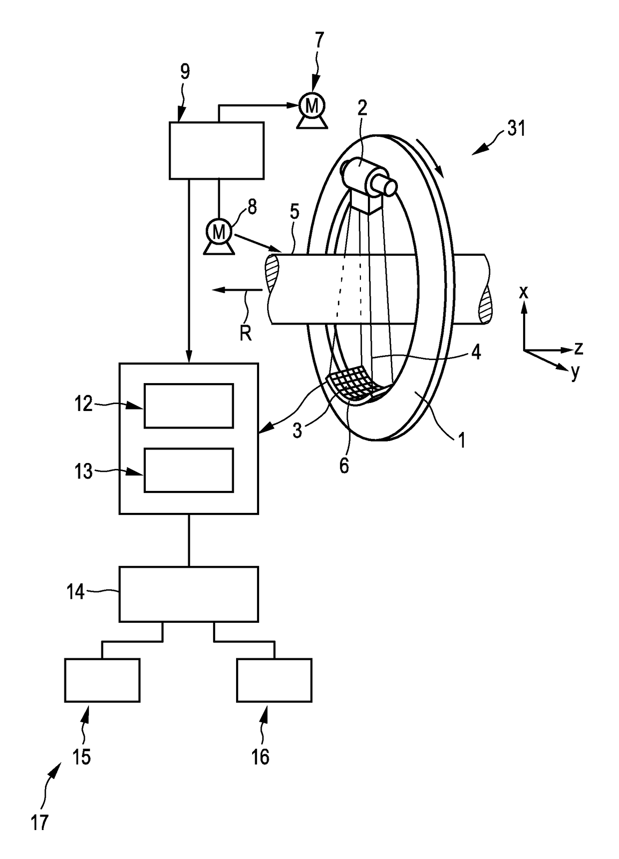
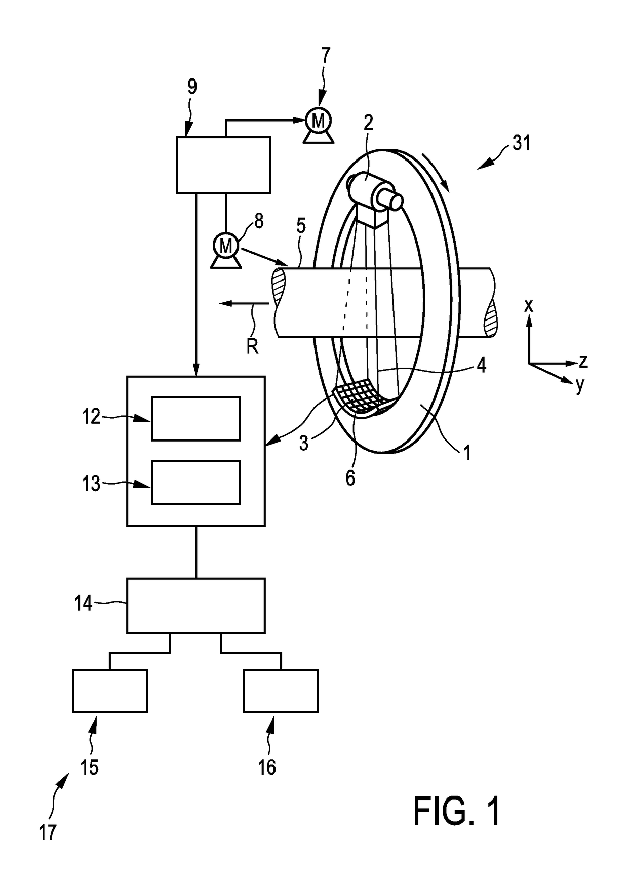
[0047]FIG. 1 shows schematically and exemplarily an embodiment of an x-ray imaging system, here, a spectrally resolving computed tomography system for generating an image of an object. The spectrally resolving computed tomography system 17 includes a support 1 which is capable of rotating about a rotational axis R which extends parallel to the z direction. An x-ray radiation device 2, which comprises an x-ray tube and which is adapted to provide polychromatic x-ray radiation 4 for traversing an examination zone 5 of the spectrally resolving computed tomography system 17 during a detection period of a scan, is mounted on the support 1. In this embodiment, the x-ray radiation device 2 is adapted to provide a conical x-ray radiation beam 4 as the polychromatic x-ray radiation. In another embodiment, the x-ray radiation device 2 can be adapted to provide the polychromatic x-ray radiation with another beam shape, for instance, with a fan beam shape. The x-ray radiation 4 traverses an obj...


PUM


Abstract

The invention relates to a photon counting x-ray radiation detection system. The system (31) comprises an x-ray radiation device (2) for providing polychromatic x-ray radiation (4) for traversing an examination zone (5) during a detection period of a scan. A photon counting detection device (6) comprising detection elements (3) detects the x-ray radiation after having traversed the examination zone and measures for each detection element photon counts in one or more energy bins during the detection period. A correction unit (12) estimates for each detection element an amount of a build up charge present in the detection element and corrects the measured photon counts for the detection element based on the estimated amount of the build up charge. This allows the corruption of the photon count rates caused by the build up charges to be compensated and to improve the determination of the photon counts.

Description

FIELD OF THE INVENTION[0001]The invention relates to a photon counting x-ray radiation detection system and method. The invention relates further to a computer program for controlling the photon counting x-ray radiation detection system as well as to an x-ray imaging system comprising the photon counting x-ray radiation detection system.BACKGROUND OF THE INVENTION[0002]Radiation detectors used for imaging applications like spectrally resolving computed tomography (CT) make use of a direct conversion material, such as cadmium telluride (CdTe), cadmium zinc telluride (CaZnTe) or silicon (Si), that is disposed between a cathode and an anode, with a voltage applied across the cathode and the anode. X-ray photons that illuminate the cathode transfer energy to electrons in the direct conversion material, which creates electron / hole pairs with the electrons drifting towards the anode. The anode, in response, produces an electrical signal that is further processed in order to measure photon...

Claims


Application Information

Patent Timeline
Patent Type & Authority Applications(United States)
IPC IPC(8): G01T1/24G01T1/29A61B6/03A61B6/00
CPCG01T1/24G01T1/29A61B6/032A61B6/4241
Inventor DAERR, HEINERTHRAN, AXEL
Owner KONINKLJIJKE PHILIPS NV
Why Eureka
Try Eureka