
High-speed autocompensation scheme of quantum key distribution

a quantum key and autocompensation scheme technology, applied in the field of information protection, can solve the problems of significant limitations on the maximum pulse repetition rate, inverse rayleigh scattering of light, and significant increase in noise signals from detectors

Active Publication Date: 2018-07-05
QRATE LLC
View PDF3 Cites 37 Cited by
  • Summary
  • Abstract
  • Description
  • Claims
  • Application Information

AI Technical Summary

Benefits of technology

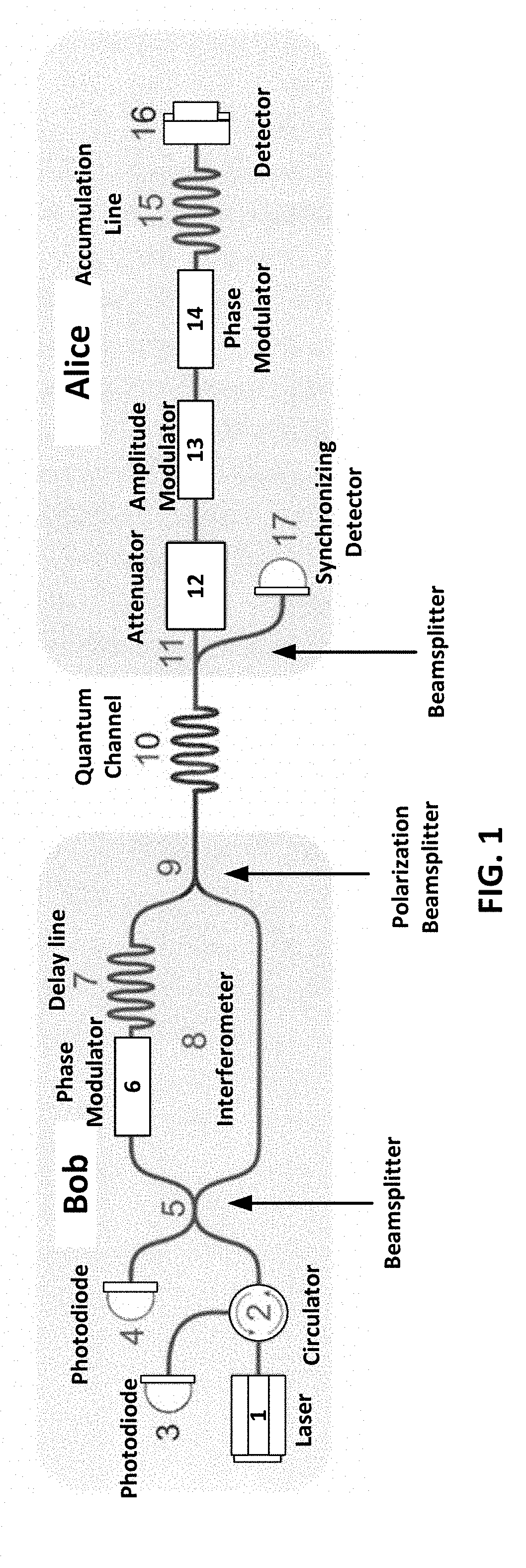
The present invention relates to information protection, and more specifically to quantum cryptography. The invention proposes an improved auto-compensation scheme for quantum key distribution, which increases the limiting frequency of the laser pulse repetition at a fixed value of their width. The technical effect of the invention is to increase the speed of key generation by excluding the intersection of pulses and reducing the time required for the pulses to travel through the phase modulator and reflect from the Faraday mirror. The invention includes a communication system for transmitting a cryptographic key between the ends of a channel, which includes a beam splitter, electro-optical attenuator, amplitude modulator, phase modulator, storage line, Faraday mirror, and synchronization detector in the transmitter, and a laser, avalanche photodiodes, beam splitter, circulator, delay line, phase modulator, polarizing beam splitter, and Mach-Zehnder interferometer in the receiver. The invention also includes a quantum channel for connecting the specified nodes.

Problems solved by technology

In such an optical scheme, when the pulses propagate in one direction and then back, the inverse Rayleigh scattering of light can significantly increase the noise signals from detectors operating in the mode of recording single photons during the generation of a quantum key.
The mutual arrangement of the phase modulator and the Faraday mirror on the sender side in the above scheme imposes significant limitations on the maximum pulse repetition rate.

Method used


Image

  • High-speed autocompensation scheme of quantum key distribution
  • High-speed autocompensation scheme of quantum key distribution
  • High-speed autocompensation scheme of quantum key distribution

Examples


Embodiment Construction

[0011]Reference will now be made in detail to the preferred embodiments of the present invention, examples of which are illustrated in the accompanying drawings.

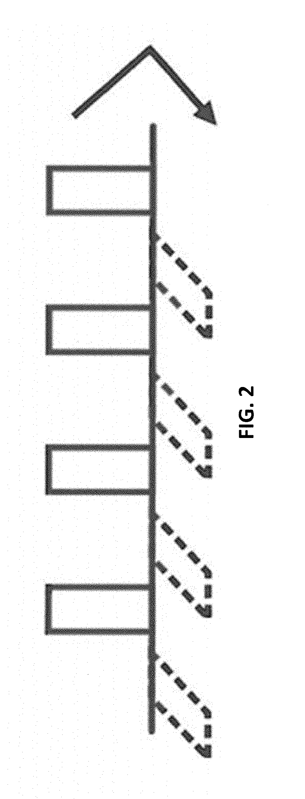
[0012]The technical result coincides with the problem and allows using the auto-compensation scheme at a frequency corresponding to a period equal to the width of the laser pulse, which is in principle the maximum possible result.

[0013]The technical result is achieved by using a communication system for transmitting a cryptographic key between the ends of a channel, where the communication system includes—

[0014]a. A transmission node (Alice) comprising a beam splitter, an electro-optical attenuator, an amplitude modulator, a phase modulator, a storage line, a Faraday mirror, and a synchronization detector;

[0015]b. A receiver node (Bob) comprising a laser, an avalanche photodiodes, beam splitter, a circulator, a delay line, a phase modulator, a polarizing beam splitter, a Mach-Zehnder interferometer; and

[0016]c. A quantum cha...


PUM


Abstract

The invention relates to quantum cryptography, and includes a communication system for transmitting a cryptographic key between the ends of a channel, including a transmitting node (Alice) comprising a beam splitter, an electro-optical attenuator, an amplitude modulator, a phase modulator, a storage line, a Faraday mirror, a synchronization detector; a receiving node (Bob) that includes avalanche photodiodes, a beam splitter, a circulator, a delay line, a phase modulator, a polarizing beam splitter, a Mach-Zehnder interferometer, and also a quantum channel for connecting these nodes. In this case, for the storage line is placed between the electro-optical phase modulator of the sender and the Faraday mirror. The limiting frequency of the laser pulse repetition at a fixed value of their width is increased, which makes it possible to use an autocompensation circuit at a frequency corresponding to the width of the laser pulse, which is the maximum possible result.

Description

CROSS-REFERENCE TO RELATED APPLICATIONS[0001]The present application claims priority to RU patent application no. 2016152338, filed on Dec. 29, 2016, which are incorporated herein by reference in their entirety.BACKGROUND OF THE INVENTIONField of the Invention[0002]The invention relates to information protection, and, more particularly, to quantum cryptography.Description of the Related Art[0003]Conventional art includes U.S. Pat. No. 6,188,768 entitled “Auto compensation scheme for the quantum distribution of a cryptographic key based on a polarization separation of light”, published Feb. 13, 2001. This patent describes basic information and technical solutions used for an auto-compensation optical scheme for quantum key distribution. In such an optical scheme, when the pulses propagate in one direction and then back, the inverse Rayleigh scattering of light can significantly increase the noise signals from detectors operating in the mode of recording single photons during the gene...

Claims


Application Information

Patent Timeline
Patent Type & Authority Applications(United States)
IPC IPC(8): H04L9/08H04B10/70H04B10/85
CPCH04L9/0852H04B10/70H04B10/85G02F1/035G02F1/225G02F2001/212H04L9/0855G02F1/212
Inventor DUPLINSKIY, ALEXANDR VALERIEVICHUSTIMCHIK, VASILY EVGENYEVICHKUROCHKIN, YURI VLADIMIROVICHKUROCHKIN, VLADIMIR LEONIDOVICHMILLER, ALEXANDER VITALIEVICH
Owner QRATE LLC
Learn More