

LED Illumination Module With Fixed Optic and Variable Emission Pattern
an illumination module and variable emission technology, applied in lighting applications, light source combinations, instruments, etc., can solve problems such as non-uniform die placement patterns relative to the optical axis of the assembly
- Summary
- Abstract
- Description
- Claims
- Application Information
AI Technical Summary
Benefits of technology
Problems solved by technology
Method used
Image

Examples
Embodiment Construction
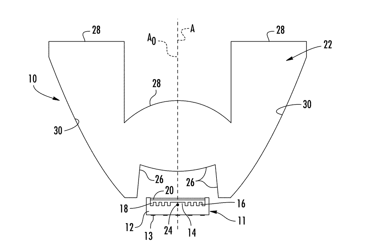
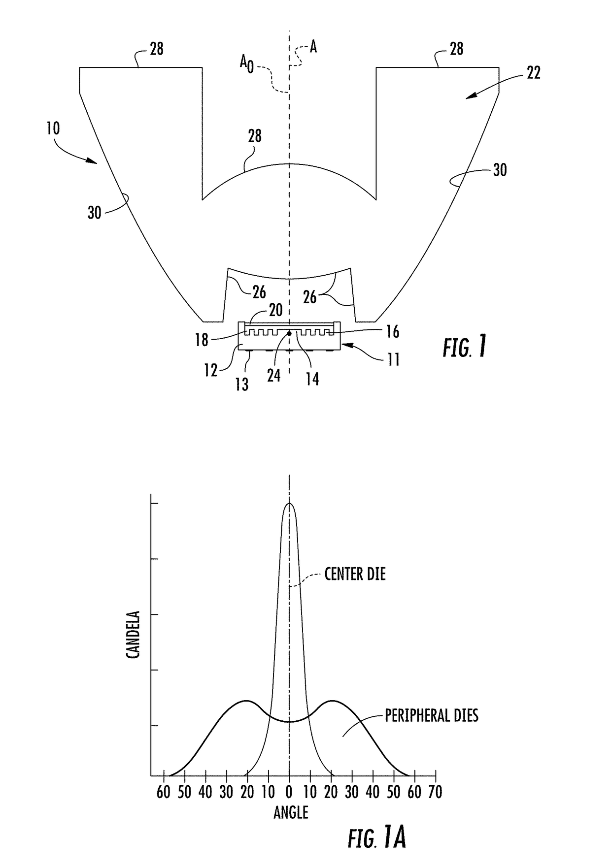
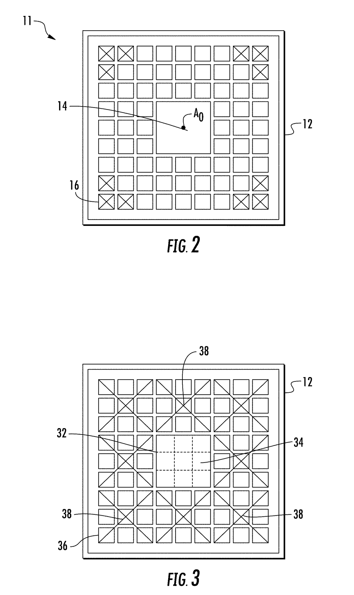
[0027]FIG. 1 is a sectional view through a first embodiment of an LED illumination module 10 incorporating aspects of the disclosure. An LED lamp 11 includes a thermally conductive ceramic substrate 12 configured to support multiple light emitting dies 14, 16. Electrically conductive pads 13 on the bottom of the substrate 12 connect the light emitting dies 12, 14 to electrical circuits on a printed circuit board (not shown). In the embodiment of FIG. 1, a single, relatively large center die 14 is positioned in the center of the ceramic substrate 12. The center die 14 in this embodiment is a square die with 1 mm sides. The center die 14 is surrounded by many small square peripheral dies 16 of about 0.2 mm a side. The shape of each die 14, 16 can be different from the disclosed square and the relative size difference between the center die 14 and the peripheral dies 16 may vary from the disclosed relationship. The dies 14, 16, may be any closed regular or irregular polygon. A YAG phos...
PUM
 Abstract
Description
Claims
Application Information