Cleaner head for a vacuum cleaner

a vacuum cleaner and cleaner head technology, applied in the direction of suction cleaners, cleaning equipment, suction nozzles, etc., can solve the problem of difficult to steer the cleaner head in a particular direction

Inactive Publication Date: 2018-07-12
DYSON TECH LTD
View PDF1 Cites 3 Cited by
  • Summary
  • Abstract
  • Description
  • Claims
  • Application Information

AI Technical Summary

Benefits of technology

[0010]The agitators may be identical and may rotate at the same speed. By employing identical agitators that rotate at the same speed, the forward traction generated by the front agitator may be

Problems solved by technology

A disadvantage with hover mode is that it can be diffic

Method used


Image

  • Cleaner head for a vacuum cleaner
  • Cleaner head for a vacuum cleaner
  • Cleaner head for a vacuum cleaner

Examples


Embodiment Construction

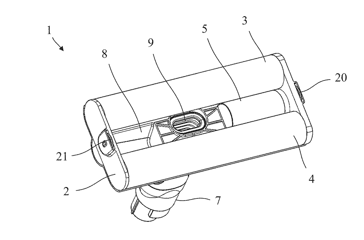
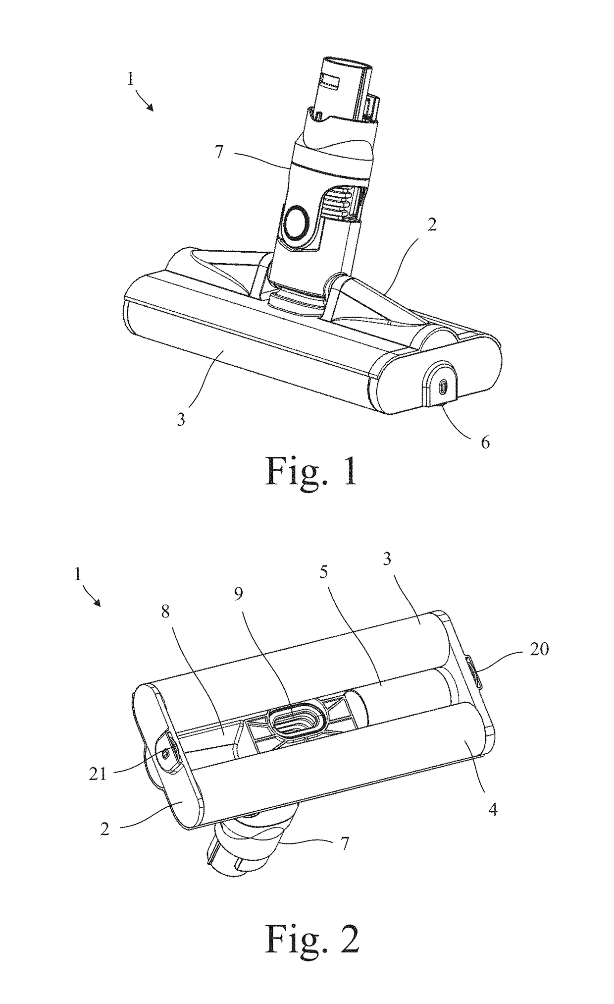
[0018]The cleaner head 1 of FIGS. 1 to 6 comprises a housing 2, a pair of agitators 3,4, a drive assembly 5, a wheel assembly 6, and a neck 7.

[0019]The housing 2 defines a chamber 8 within which the agitators 3,4 are rotatably mounted. Each agitator 3,4 comprises an elongate body 11 to which bristles, flicker strips or other means 12 for agitating a surface are attached. In the present embodiment, the elongate body 11 is covered with a plush of synthetic fibres 12. The two agitators 3,4 rotate in opposite directions about axes of rotation 13,14 that are parallel to one another. More particularly, the agitators 3,4 rotate in directions that act to sweep dirt from the floor into the chamber 8. Consequently the front agitator 3 in FIGS. 5 and 6 rotates in a counter-clockwise direction and the rear agitator 4 rotates in a clockwise direction.

[0020]The drive assembly 5 is mounted within the housing 2 and comprises an electric motor 15 and a gear train 16 for transmitting torque generated...


PUM


Abstract

A cleaner head for a vacuum cleaner that comprises a pair of rotary agitators and one or more wheels. The agitators rotate in opposite directions, and the wheels are moveable between a deployed position and a retracted position. The wheels contact a floor to be cleaned when in the deployed position, and the wheels are lifted clear of the floor when in the retracted position such that the cleaner head is supported on the floor solely by the agitators.

Description

REFERENCE TO RELATED APPLICATIONS[0001]This application claims priority to United Kingdom Application No. 1700330.2, filed Jan. 9, 2017, the entire contents of which are incorporated herein by reference.FIELD OF THE INVENTION[0002]The present invention relates to a cleaner head for a vacuum cleaner.BACKGROUND OF THE INVENTION[0003]The cleaner head of a vacuum cleaner may comprise a rotary agitator mounted within a housing. Wheels are often provided on the base of the housing to ensure that, as the cleaner head is manoeuvred over a floor, the housing does not contact and potentially damage the floor. Unfortunately, the wheels tend to constrain movement of the cleaner head to forward and rearward motion only.SUMMARY OF THE INVENTION[0004]According to some embodiments, a cleaner head comprises a pair of rotary agitators and one or more wheels, wherein the agitators rotate in opposite directions, the wheels are moveable between a deployed position and a retracted position, the wheels co...

Claims


Application Information

Patent Timeline
IPC IPC(8): A47L9/04A47L9/06
CPCA47L9/0477A47L9/066A47L9/04A47L9/0405A47L9/0433A47L9/009A47L9/0411A47L9/0416A47L9/0494A47L9/2852
Inventor DODGSON, OLIVER
Owner DYSON TECH LTD
Why Eureka
Try Eureka