Device and method for processing a signal in the frequency domain

a frequency domain and signal technology, applied in the field of audio signals, can solve the problems of increasing computing burden, difficult to combine with gradual filter crossfading, and high latencies of filtering, and achieve the effect of increasing efficiency

Active Publication Date: 2018-07-12
BRANDENBURG LABS GMBH
View PDF3 Cites 1 Cited by
  • Summary
  • Abstract
  • Description
  • Claims
  • Application Information

AI Technical Summary

Benefits of technology

[0018]A plurality of necessitated time-domain windowing functions are very easy to approximate by such window functions, the frequency-domain representation of which comprises only a few non-zero coefficients. This means that the circular convolution may be performed so efficiently that the gain by saving the additional frequency-to-time domain transforms exceeds the costs of the circular convolution in the frequency domain. In embodiments of the present invention which deal with fading-in, fading-out, crossfading or changing the volume, a considerable reduction in complexity may be achieved particularly by solely approximating a time-domain window function in the frequency domain, that is by restricting the number of coefficients to, for example, less than 18 coefficients in the frequency domain. Additional gains in efficiency may be achieved by efficient computing rules for the circular convolution by making use of the structure of the frequency-domain window function. On the one hand, this applies to the conjugate-symmetrical structure of this window function which results from the real-valuedness of the respective-time domain window function. On the other hand, summands of the circular convolution sum may be calculated more efficiently when the respective coefficients of the frequency-domain window function are of purely real value or purely imaginary.

Problems solved by technology

Frequency-domain convolution algorithms, such as Overlap-Add and Overlap-Save (among others [8]; [9]), partition only the input signal, but not the filter and consequently use large FFTs (Fast Fourier Transform), resulting in high latencies when filtering.
However, it is common to all methods of fast convolution that they are only very difficult to combine with gradual filter crossfading.
On the other hand, interpolation of intermediate values between different filters, as arise in the case of a transition, would result in a considerably increased computing burden, since these interpolated filter sets each first have to be transformed to a form suitable for applying fast convolution algorithms (this usually necessitates segmentation, zero padding and an FFT Operation).
For “smooth” crossfading, these operations have to be performed quite frequently, thereby considerably reducing the performance advantage of fast convolutions.
Crossfading or fading-in or fading-out signals is not provided for there as an application; in addition, the method described there is based on fixed 3-elements frequency-domain windows which are based on windows known in DSP, and does not exhibit a flexibility in order to adjust complexity and quality of the approximation to a predetermined window function (and, consequently, nor does the design method for the sparsely occupied window functions).
Rendering dynamic acoustic scenes, in that dynamic head movements of the listeners are also considered, improves the localizing quality, realism and plausibility of binaural synthesis considerably, but also increases the computing complexity as regards rendering.
Again, such techniques increase the complexity of binaural rendering considerably.
Due to the conventionally large number of sound objects, filtering the source signals by the HRTFs contributes considerably to the complexity of binaural synthesis.
A common disadvantage of all the FD convolution methods is that an exchange of filter coefficients or a gradual transition between filters is restricted more strongly and usually necessitates a higher computing complexity than crossfading between time-domain filters.
On the other hand, the requirement of transferring the filters to a frequency-domain representation entails a considerable reduction in performance with frequent filter changes.
In such algorithms and other applications, the time-to-frequency transform algorithms and the inverse frequency-to-time domain transform algorithms are so complicated that a convolution in the frequency domain using a frequency-domain windowing function justifies the complexity.

Method used


Image

  • Device and method for processing a signal in the frequency domain
  • Device and method for processing a signal in the frequency domain
  • Device and method for processing a signal in the frequency domain

Examples


Embodiment Construction

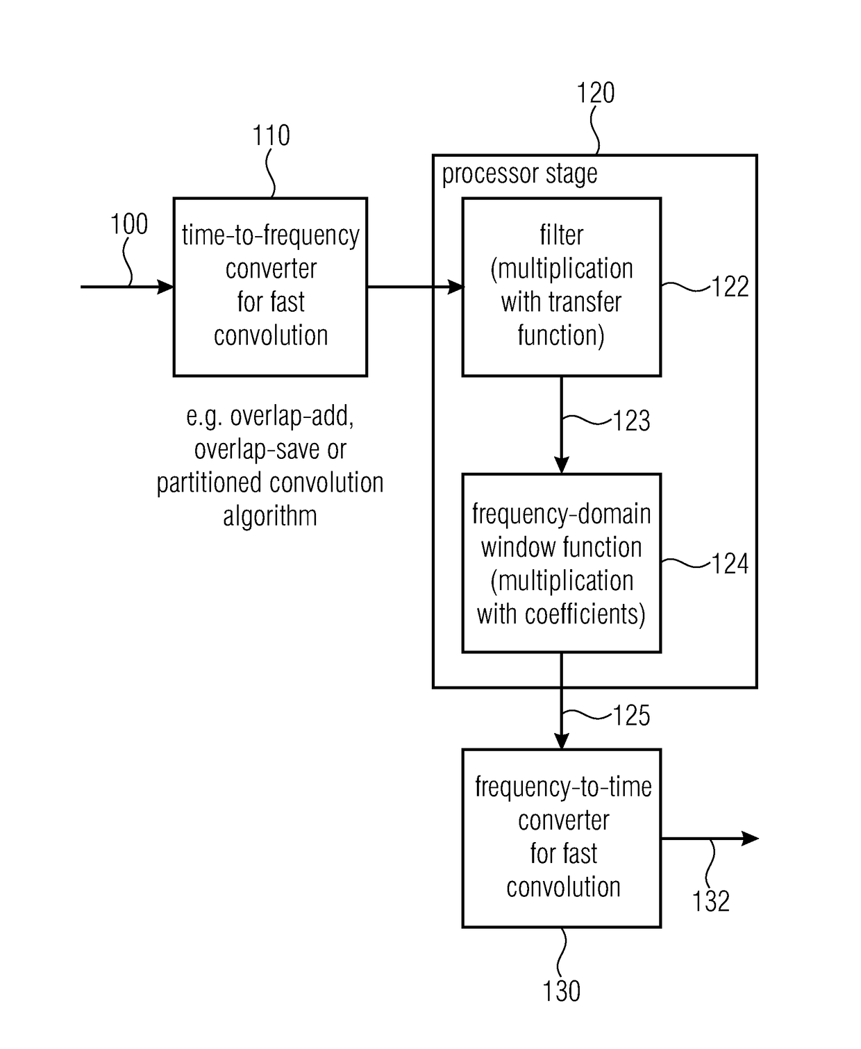
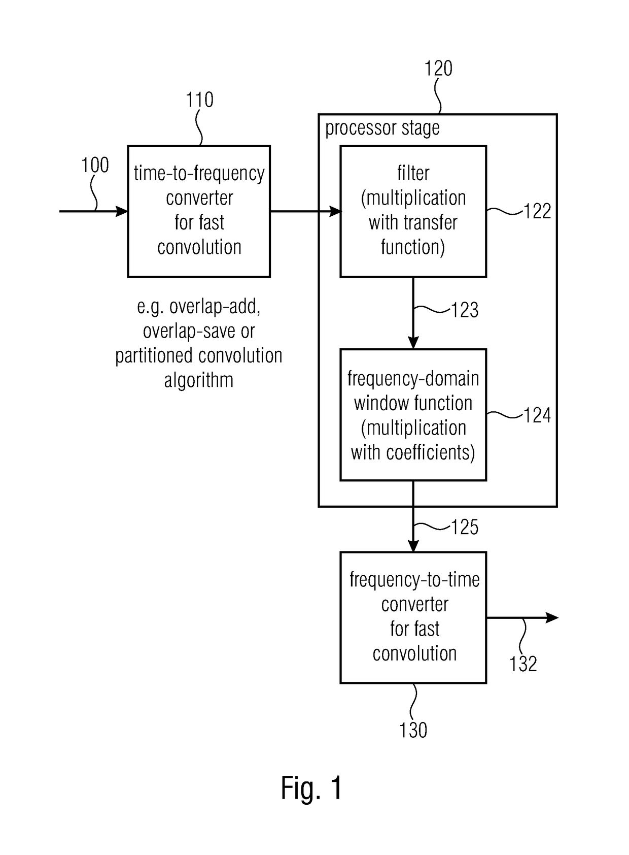
[0038]FIG. 1 shows a device for processing a discrete-time signal in the frequency domain. An input signal 100 which is present in the time domain is fed to a time-to-frequency converter 110. The output signal of the time-to-frequency converter 110 is then fed to a processor stage 120 which comprises a filter 122 and frequency-domain window function providing means 124. The output signal 123 of the frequency-domain window function providing means 124 may then be fed, either directly or after processing, such as, for example, a combination with other correspondingly, equally processed signals, to frequency-time transform means or frequency-time converter 130. In an embodiment of the present invention, the time-to-frequency converter 110 and the frequency-time converter 130 are designed for fast convolution. A fast convolution may, for example, be an overlap-add convolution algorithm, an overlap-save convolution algorithm or any partitioned convolution algorithm. Such a partitioned co...


PUM


Abstract

A device for processing a signal includes a processor stage configured to filter the signal present in a frequency-domain representation by a filter with a filter characteristic in order to obtain a filtered signal, to provide the filtered or a signal derived from the filtered signal with a frequency-domain window function, in order to obtain a windowed signal, wherein providing has multiplications of frequency-domain window coefficients of the frequency-domain window function by spectral values of the filtered signal or the signal derived from the filtered signal in order to obtain multiplication results, and summing up the multiplication results. Further, the device has a converter for converting the windowed signal or a signal determined using the windowed signal to a time domain in order to obtain the processed signal.

Description

CROSS-REFERENCE TO RELATED APPLICATIONS[0001]This application is a continuation of U.S. patent application Ser. No. 15 / 264,756, filed on Sep. 14, 2016, which is a continuation of copending International Application No. PCT / EP2015 / 055094, filed Mar. 11, 2015, which is incorporated herein by reference in its entirety, and additionally claims priority from European Application No. 14159922.5, filed Mar. 14, 2014, and from German Application No. 102014214143.5, filed Jul. 21, 2014, which are also incorporated herein by reference in their entirety.BACKGROUND OF THE INVENTION[0002]The present invention relates to processing signals and, in particular, audio signals in the frequency domain.[0003]In many fields of signal processing, filter characteristics are changed at runtime. Frequently, a gradual smooth transition is necessitated here to prevent interferences by switching (for example, discontinuities in the signal path, in the case of audio signals audible click artifacts). This may be...

Claims


Application Information

Patent Timeline
Patent Type & Authority Applications(United States)
IPC IPC(8): H04S7/00H04S3/00G10L19/022
CPCH04S7/307G10L19/022H04S3/004H04S2400/01H04S7/30H04S2420/01
Inventor FRANCK, ANDREAS
Owner BRANDENBURG LABS GMBH
Why Eureka
Try Eureka