Vapor relief strainer with cleaner

a strainer and cleaner technology, applied in the field of vapor cleaning, can solve the problems of affecting the performance affecting the efficiency of the filter screen, so as to reduce the impact and mitigate the fatigue and wear of the filter screen

Active Publication Date: 2018-07-26
ANDRITZ INC
View PDF6 Cites 15 Cited by
  • Summary
  • Abstract
  • Description
  • Claims
  • Application Information

AI Technical Summary

Benefits of technology

[0013]The present disclosure describes a vapor relief strainer cleaning assembly comprising a turbine configured to power a dislodger assembly. Exemplary vapor relief strainer cleaning assemblies may use an existing vapor source (e.g. a power boiler) to power the vapor relief strainer cleaning assembly. Operators may collect and reuse the vapor used to power the relief strainer cleaning assembly elsewhere in the process, thereby reducing the impact of the exemplary vapor relief strainer cleaning assembly as a net energy consumer in the production system. In addition, a portion of the excess vapor used to power the vapor relief strainer cleaning assembly may be used as a dislodging means, thereby avoiding the need for physical contact between the dislodge and the inner wall of the filter screen in certai...

Problems solved by technology

These contaminants can be abrasive and can contribute to premature system wear if improperly filtered.
Furthermore, unfiltered contaminants can occlude system conduits.
Over time, contaminants occlude the filter screen and disrupt the screening process.
As a result, the blowback method subjects the vapor relief strainer to pressures that exceed the vapor relief strainer's nominal operating capacity.
Furthermore, the blowback method tends to have limited effectiveness in cleaning the filter screen.
Contaminants tend to be wet and clumped together on the filter screen.
As a result, the blowback method ineffectively cleans the total surface area of the filter screen.
That is, the blowback method typically creates localized contaminant-free areas on the filter screen that are located close to the blowback conduit along the path of the blowback steam.
Furthermore, a typical vapor relief strainer is generally not designed to...

Method used


Image

  • Vapor relief strainer with cleaner
  • Vapor relief strainer with cleaner
  • Vapor relief strainer with cleaner

Examples


Embodiment Construction

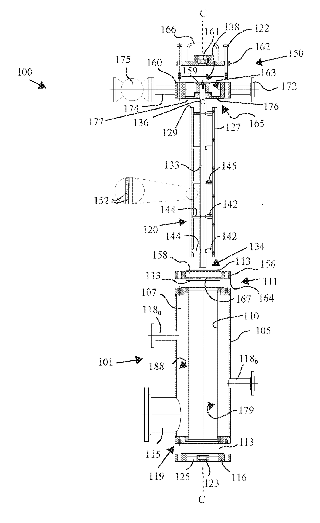
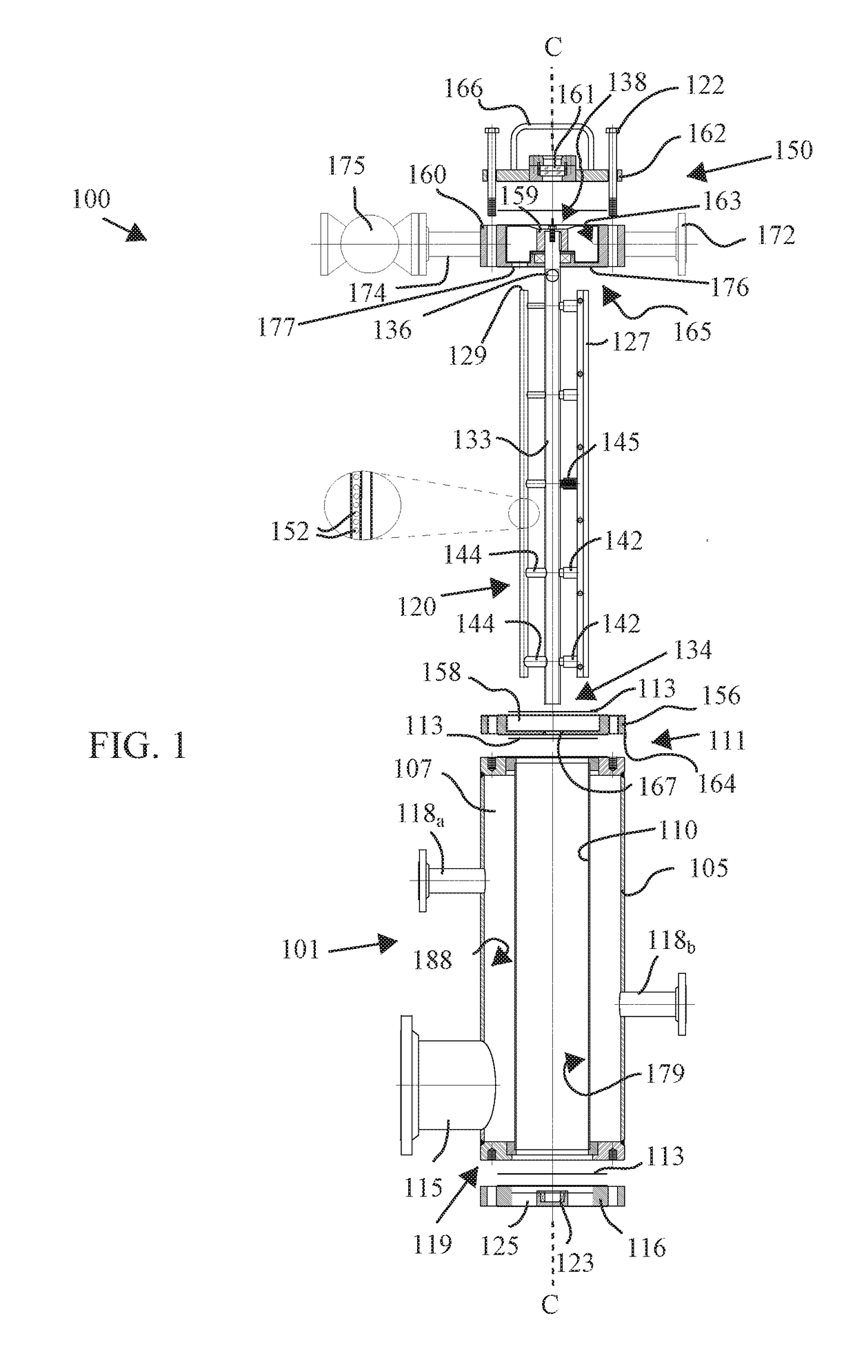
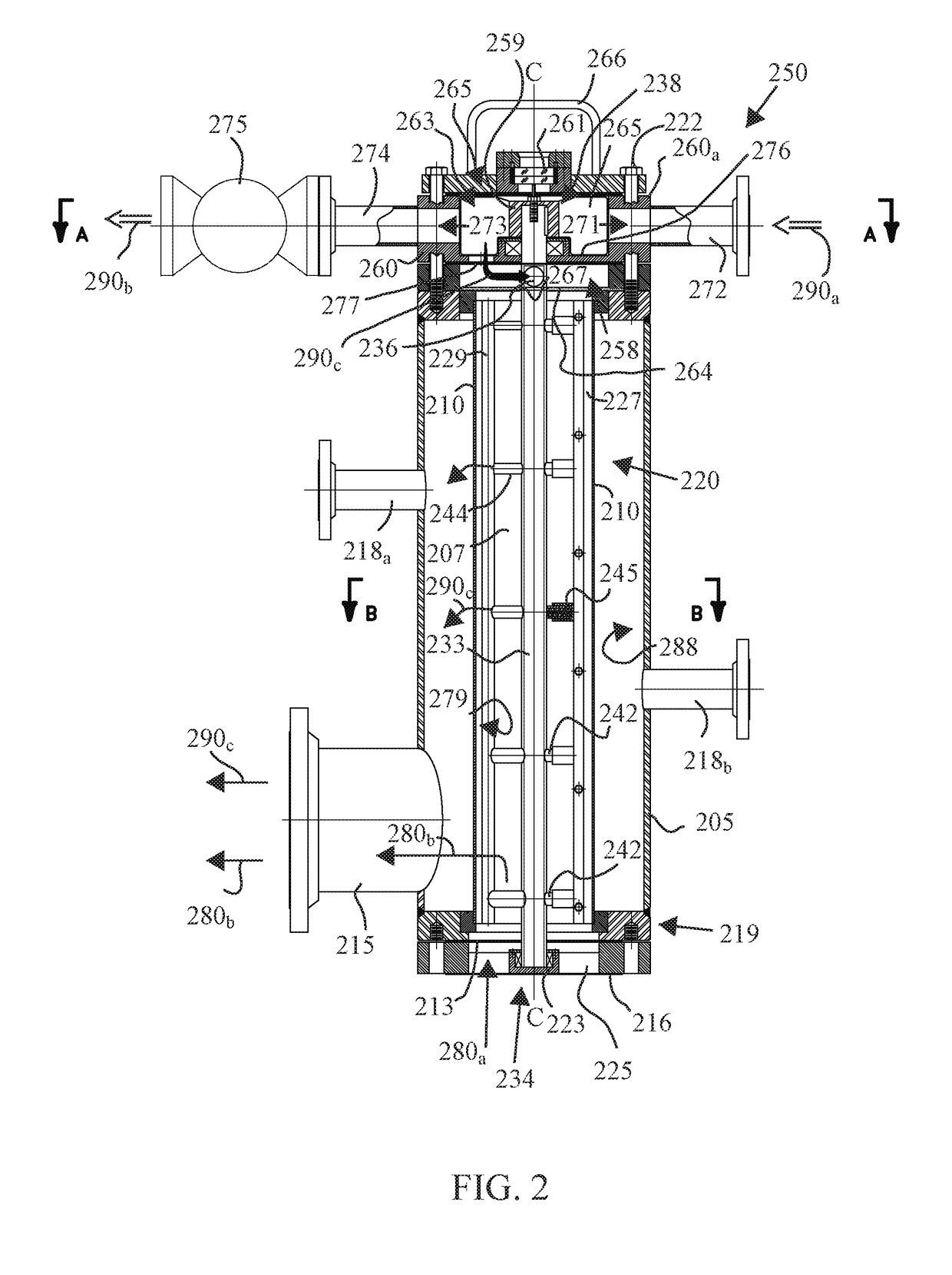
[0025]The following detailed description of the preferred embodiments is presented only for illustrative and descriptive purposes and is not intended to be exhaustive or to limit the scope and spirit of the invention. The embodiments were selected and described to best explain the principles of the invention and its practical application. One of ordinary skill in the art will recognize that many variations can be made to the invention disclosed in this specification without departing from the scope and spirit of the invention.

[0026]Corresponding reference characters indicate corresponding parts throughout the several views. Although the drawings represent embodiments of various features and components according to the present disclosure, the drawings are not necessarily to scale and certain features may be exaggerated in order to better illustrate embodiments of the present disclosure, and such exemplifications are not to be construed as limiting the scope of the present disclosure ...


PUM

PropertyMeasurementUnit
Angleaaaaaaaaaa
Widthaaaaaaaaaa
Areaaaaaaaaaaa

Abstract

A vapor relief strainer cleaning assembly comprising a turbine and dislodger assembly, wherein the turbine is configured to move a dislodger assembly disposed within a vapor screen relief vessel. Exemplary dislodger assemblies are configured to be powered by vapor or gas and to use excess vapor or gas optionally to dislodge non-condensable contaminants from the filter screen or to facilitate contaminant dislodgement from the inner wall of the filter screen.

Description

CROSS-RELATED APPLICATION[0001]This application is a non-provisional utility application that claims the benefit under 35 U.S.C. § 119(e) of U.S. Provisional Patent Application No. 62 / 448,449 filed on Jan. 20, 2017, the entirety of which is incorporated herein by reference.BACKGROUND OF THE INVENTION1. Technical Field[0002]The present disclosure relates generally to vapor cleaning in industrial processes and more particularly to vapor relief strainers configured to filter impurities from vapor exposed to fibers, fines, and other non-condensable contaminants borne from processing lignocellulosic material.2. Related Art[0003]Several chemical, mechanical, and biological engineering processes, including the production of pulp and paper from lignocellulosic material, utilize steam vapor to facilitate production. For example in chemical pulping, operators may introduce steam into the chip bin to displace entrapped air in the lignocellulosic material. A steaming vessel then pre-heats the l...

Claims


Application Information

Patent Timeline
IPC IPC(8): B01D29/64D21C11/06
CPCB01D29/6476D21C11/066B01D46/2403B01D46/00D21C9/02D21C11/06B01D46/681
Inventor NELLIS, WALTER E.
Owner ANDRITZ INC
Why Eureka
Try Eureka