
Wireless Charging Device for Vehicle

a charging device and vehicle technology, applied in the direction of charging devices for exchanging data, inductances, transportation and packaging, etc., can solve the problems of affecting the safety of passengers and damage to the interior of the vehicle, and achieve the elimination of the risks of heat generated during the wireless charging operation performed in the vehicle, and the effect of facilitating wireless charging

Inactive Publication Date: 2018-07-26
LG INNOTEK CO LTD
View PDF3 Cites 6 Cited by
  • Summary
  • Abstract
  • Description
  • Claims
  • Application Information

AI Technical Summary

Benefits of technology

The patent describes a method and device that allows for wireless charging in vehicles. This allows for better control of the charging process and reduces risks to occupant safety due to heat generated during the charging. The benefits of this invention are improved safety and convenience for wireless charging in vehicles.

Problems solved by technology

Heat generated inside the vehicle may damage the interior of the vehicle or threaten the safety of passengers.

Method used


Image

  • Wireless Charging Device for Vehicle
  • Wireless Charging Device for Vehicle
  • Wireless Charging Device for Vehicle

Examples


Embodiment Construction

[0039]Hereinafter, an apparatus and various methods to which embodiments of the present disclosure are applied will be described in detail with reference to the drawings. As used herein, the suffixes “module” and “unit” are added or used interchangeably to facilitate preparation of this specification and are not intended to suggest distinct meanings or functions.

[0040]In the description of the embodiments, it is to be understood that, when an element is described as being “on” or “under” another element, it can be directly “on” or “under” another element or can be indirectly formed such that one or more other intervening elements are also present between the two elements. The expression “on” or “under” may represent not only an upward direction but also a downward direction with respect to one element.

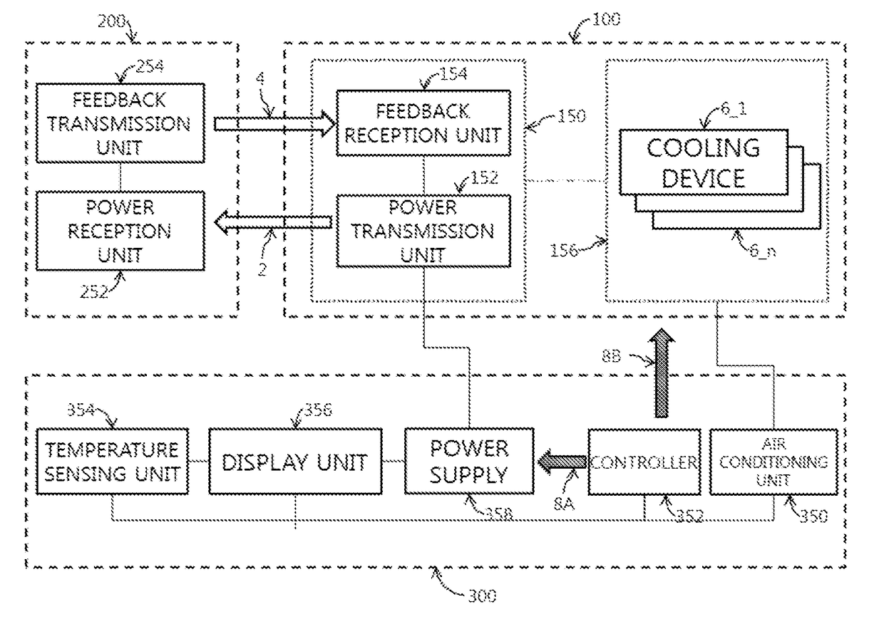
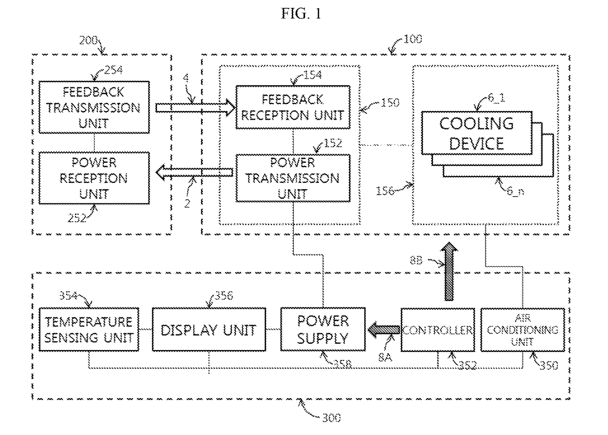
[0041]FIG. 1 illustrates a first wireless charging system for vehicles.

[0042]As shown in the figure, the first wireless charging system for vehicles may include a wireless power transm...


PUM

PropertyMeasurementUnit
thickness Tmcaaaaaaaaaa

Abstract

The present invention provides a wireless power transmitting device comprising: a power transmission unit which transmits a wireless power signal to a subject being charged; a feedback reception unit which receives a feedback signal transferred from the subject being charged, and controls the power transmission unit; and a cooling unit which is positioned on the periphery of the power transmission unit, and absorbs heat.

Description

TECHNICAL FIELD[0001]Embodiments relate to a wireless charging device, and more particularly, to a wireless charging device mountable in a vehicle.BACKGROUND ART[0002]Wireless charging is a technique of charging a battery by causing current to flow through electromagnetic induction. In this technique, a magnetic field generated in a primary coil of a charging pad induces current in a secondary coil of the battery part. This technique is suitable for portable communication devices and electric vehicles that require a large capacity battery. In addition, with this technique, contacts are not exposed to the outside. Accordingly, there is almost no risk of electric leakage and poor charging caused by the wired charging technique may be prevented.[0003]As wireless charging technology has become entrenched, various charging pads have been developed to provide wireless charging power signals. Generally, a charging pad includes a coil or antenna for transmitting a wireless charging power si...

Claims


Application Information

Patent Timeline
Patent Type & Authority Applications(United States)
IPC IPC(8): H02J7/02H01F38/14H01F27/28H10N10/17
CPCH02J7/025H01F38/14H01F27/2876H01L35/32H04W4/80H04B5/0075B60H1/00B60R16/03H02J7/00H02J7/02H05K7/20H02J50/10H02J7/00036H02J7/00047H02J7/007192H10N10/17H04B5/24
Inventor KWON, YONG ILKIM, SEUNG TAELEE, JAE KYU
Owner LG INNOTEK CO LTD
Learn More