
Hall-effect thruster usable at high altitude

a high-altitude, thruster technology, applied in the direction of machines/engines, cosmonautic vehicles, transportation and packaging, etc., can solve the problems of limited lifetime, thrusters cannot operate above an altitude near 100 km, and cannot be usable at altitudes higher than 100 km

Active Publication Date: 2018-08-02
SN DETUDE & DE CONSTR DE MOTEURS DAVIATION S N E C M A
View PDF0 Cites 2 Cited by
  • Summary
  • Abstract
  • Description
  • Claims
  • Application Information

AI Technical Summary

Benefits of technology

The patent describes a device called a concentrator that collects particles from the atmosphere and concentrates them in a smaller volume. This allows for a higher density of particles in a specific area, which can be used to provide thrust for a spacecraft. The concentrator is designed to protect the rear of the spacecraft from ion and particle impacts, which can damage it. Overall, the device helps to compensate for the low density of particles at high altitude by collecting and concentrating them into a smaller area, allowing for efficient space travel.

Problems solved by technology

At this altitude, the residual atmosphere slows the satellites, which limits their lifetime.
However, taking into account the atmospheric rarefaction with altitude, these thrusters cannot operate above an altitude near 100 km.
They are therefore not usable at altitudes higher than this, such as for example to allow the transfer of satellites toward higher orbits.

Method used


Image

  • Hall-effect thruster usable at high altitude
  • Hall-effect thruster usable at high altitude
  • Hall-effect thruster usable at high altitude

Examples


first embodiment

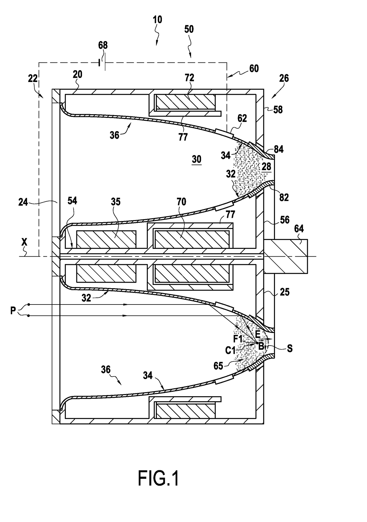
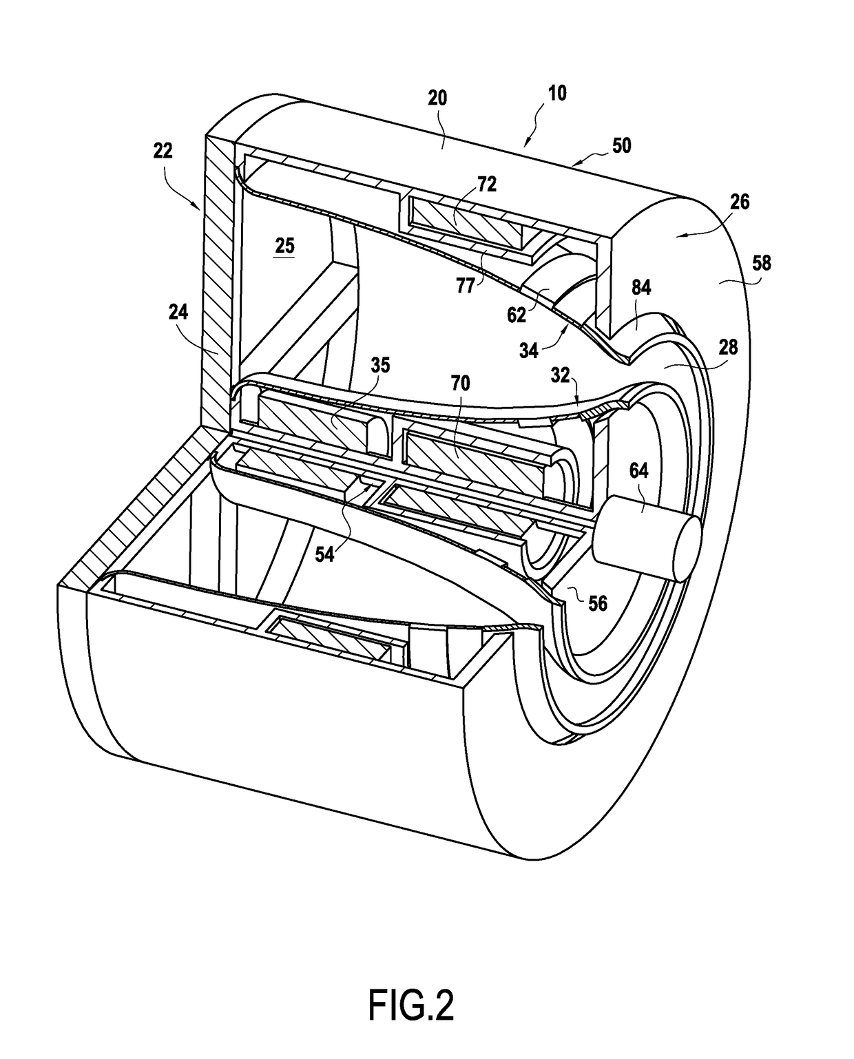
[0069]The first embodiment illustrates the first aspect of the invention in relation to FIGS. 1 and 2.

[0070]FIGS. 1 and 2 show the thruster 10 of the satellite 1 (an example of a spacecraft), which is a Hall-effect thruster with atmospheric gas as a propellant.

[0071]The thruster 10 has a rotationally symmetrical shape overall around a thrust axis X. It is arranged inside a casing 20 with a substantially cylindrical shape with axis X. The upstream end 22 of this casing is open while the other end 26 (downstream end) is partially closed by a substantially flat bottom 25 perpendicular to the axis X. The bottom 25 is crossed however, by an annular particle ejection passage 28.

[0072]The bottom 25 has the general shape of a disk perpendicular to the axis X. Due to the presence of the passage 28, the bottom 25 consists of a disk 56 and an annular area 58 situated radially around the annular passage 28. The annular area 58 is formed integrally with the rest of the casing 20.

[0073]Inside the...

second embodiment

[0114]The second embodiment, which illustrates the second aspect of the invention, will now be presented in relation with FIGS. 3 and 4.

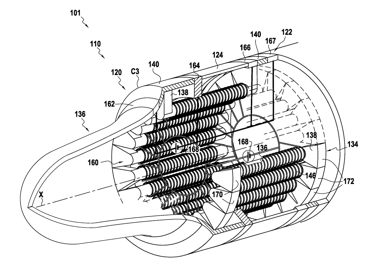
[0115]FIG. 3 represents a satellite 101, including a Hall-effect thruster 110 according to the invention.

[0116]The satellite 101 is arranged in an exterior casing 120 which has a rotationally symmetrical shape around an axis X. The thruster 110 is arranged inside the outer wall 122 of the casing 120.

[0117]The thruster 110 has an axisymmetric structure around the axis X. The terms “upstream” and “downstream,” in the present context, are defined with respect to the normal direction of circulation of the satellite and therefore of the thruster.

[0118]The wall 122 has two portions, namely a particle concentrator 136, which serves to concentrate the particles P located on the trajectory of the satellite 101 or in the vicinity of it, and a rear portion 124 situated downstream of the concentrator 136.

[0119]The shape of the concentrator 136 is defined by a c...


PUM


Abstract

A Hall-effect thruster (10), configured to be arranged inside or outside a spacecraft.The thruster has a concentrator (36) for collecting particles (P).The shape of the concentrator is defined by a continuous contour (C1) wrapped around the thrust axis and is such that on a major portion of the contour, each section of the concentrator perpendicular to the contour has a parabolic shape and has a focus (F1) belonging to the contour (C1).In addition, the magnetic circuit (50) is arranged so as to generate the magnetic field (B) in the vicinity of the contour (C1).

Description

FIELD OF THE INVENTION[0001]The present invention relates to the field of Hall-effect thrusters with atmospheric gas as propellant.TECHNICAL BACKGROUND[0002]Document US2003 / 046921 describes a Hall-effect thruster with atmospheric gas as propellant. Such a thruster uses particles of the residual atmosphere in which it maneuvers to operate.[0003]Hall-effect thrusters with atmospheric gas as the propellant are mainly used to propel observation satellites; these thrusters are particularly useful in low orbit.[0004]At this altitude, the residual atmosphere slows the satellites, which limits their lifetime. Advantageously, Hall-effect thrusters with atmospheric gas as the propellant allow this drag to be compensated, which thus increases the lifetime of the satellites.[0005]However, taking into account the atmospheric rarefaction with altitude, these thrusters cannot operate above an altitude near 100 km. They are therefore not usable at altitudes higher than this, such as for example to ...

Claims


Application Information

Patent Timeline
Patent Type & Authority Applications(United States)
IPC IPC(8): F03H1/00B64G1/40
CPCF03H1/0075B64G1/405F03H1/0012B64G1/413
Inventor MARCHANDISE, FREDERIC RAPHAEL JEANZURBACH, STEPHAN
Owner SN DETUDE & DE CONSTR DE MOTEURS DAVIATION S N E C M A
Learn More