Applying equalized plasma coupling design for mura free susceptor

a plasma coupling and mura free technology, applied in the direction of solid-state diffusion coating, chemical vapor deposition coating, coating, etc., can solve the problems of discontinuity marks, non-uniform plasma distribution, and uneven film deposited quality, and achieve the effect of minimizing or eliminating discontinuity marks in the substra

Inactive Publication Date: 2018-08-02
APPLIED MATERIALS INC
View PDF0 Cites 10 Cited by
  • Summary
  • Abstract
  • Description
  • Claims
  • Application Information

AI Technical Summary

Benefits of technology

[0008]Embodiments described herein relate to biasing or grounding of one or more lift pins used for large area substrate handling in order to eliminate, or minimize, the appearance of discontinuity marks in the substrate from unequal distribution of the plasma formed thereabove.

Problems solved by technology

If the plasma distribution above the surface of a substrate is not generally uniform, then the quality of the film deposited will not be uniform.
One source of non-uniform plasma distribution is unequal energy coupling with the plasma above substrate lift pins disposed in the substrate support.
Unfortunately, discontinuity marks (visible disruptions in the appearance of the deposited film, also known as golf tee mura) are commonly found on the processed substrate in regions disposed above and, or, proximate to the lift pins.
However, the discontinuity marks in the large area substrate remain undesirable as they result in wasted substrate surface area and, therefore, increased manufacturing costs.
Further, processes designed to avoid discontinuity marks in the center of a substrate require additional patterning steps and procedures that increase overall manufacturing time.
In applications that require large continuous substrate areas, such as large screen television production, such discontinuity marks cannot be avoided.

Method used


Image

  • Applying equalized plasma coupling design for mura free susceptor
  • Applying equalized plasma coupling design for mura free susceptor
  • Applying equalized plasma coupling design for mura free susceptor

Examples


Embodiment Construction

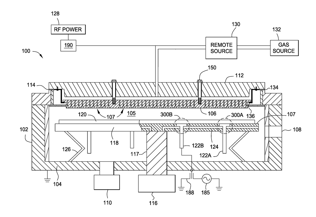
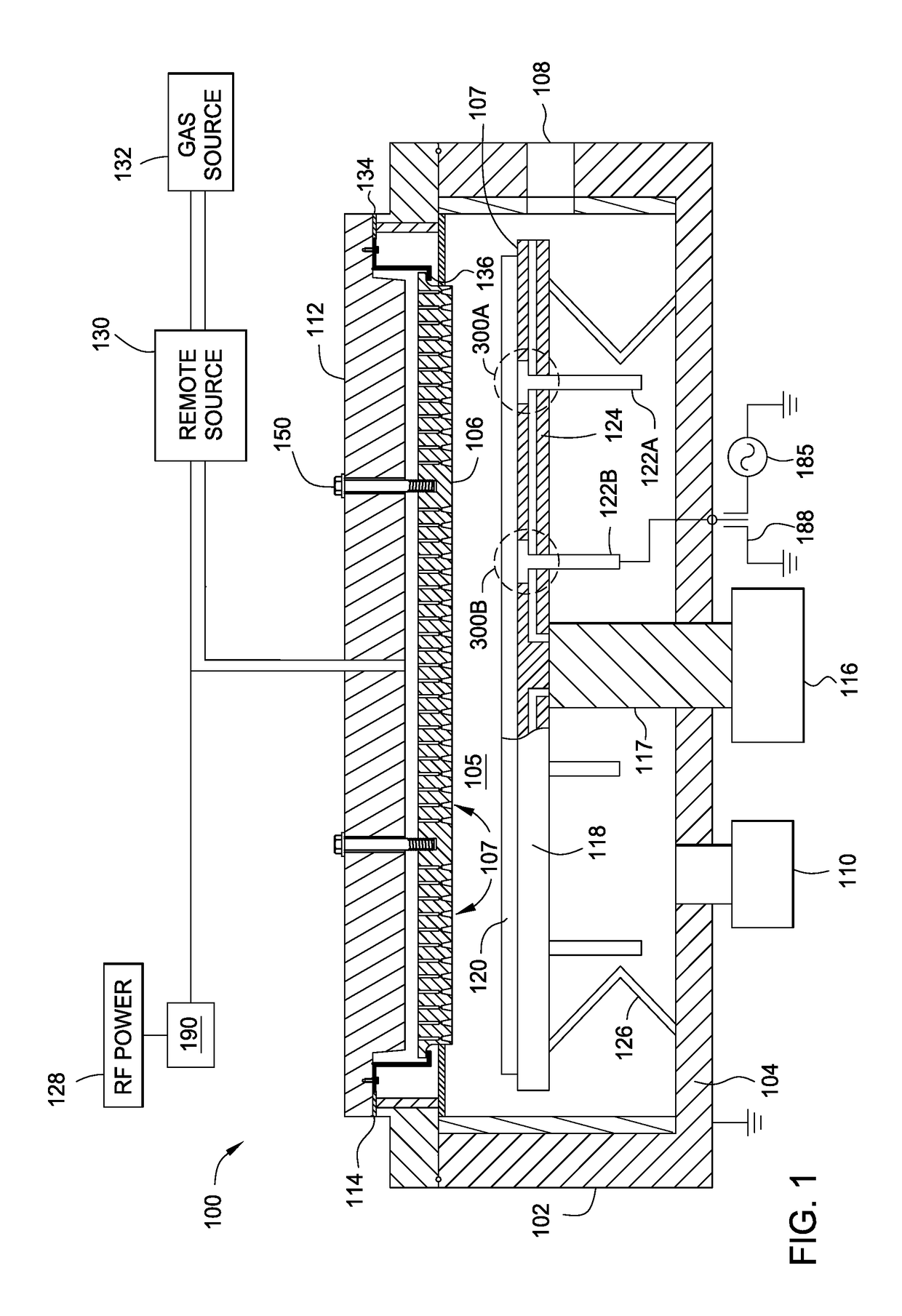
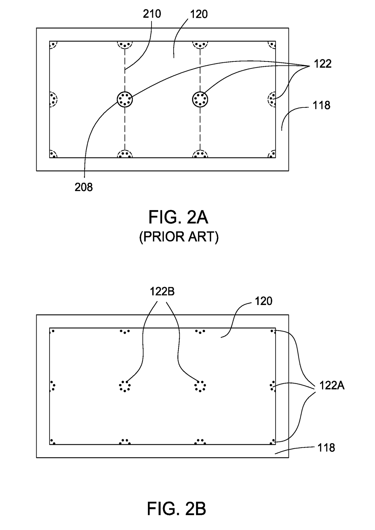
[0019]Embodiments described herein generally relate to methods and apparatus for equalizing plasma distribution above a substrate support in order to eliminate or minimize discontinuity marks formed during plasma enhanced chemical vapor deposition (PECVD) of a material layer onto a large area substrates. Discontinuity marks, corresponding to lift pin configurations in the substrate support, can be eliminated or minimized by biasing or by grounding desired lift pins. To prevent shorting between biased or grounded lift pins and the substrate support, the lift pins are electrically isolated from the substrate support. In one embodiment, one or more biased or grounded lift pins are electrically isolated from the substrate support by an electrically insulating material disposed on surfaces of the one or more lift pins. In another embodiment, one or more lift pins are electrically isolated from the substrate support by an electrically insulating material disposed on the walls of one or mo...


PUM

PropertyMeasurementUnit
surface areaaaaaaaaaaa
volumeaaaaaaaaaa
bias potentialaaaaaaaaaa

Abstract

A method and apparatus for equalized plasma coupling is provided herein. Discontinuity marks, also known as golf tee mura, are eliminated or minimized by biasing or grounding lift pins disposed in openings towards the center of a substrate support. To prevent shorting between a biased or grounded lift pin and the substrate support, lift pins are electrically isolated from the substrate support. The electrical isolation of the lift pin includes coating the lift pins with an electrically insulating material or lining a respective substrate support opening with an electrically insulating material.

Description

CROSS-REFERENCE TO RELATED APPLICATIONS[0001]This application claims priority to U.S. Provisional Patent Application Ser. No. 62 / 453,725 filed on Feb. 2, 2017, which is herein incorporated by reference in its entirety.BACKGROUNDField[0002]Embodiments of the present disclosure generally relate to a substrate support used in flat panel display manufacturing. More particularly, embodiments of the disclosure relate to substrate lift pins for use in a vacuum chamber utilized to deposit materials on flat media, such as rectangular, flexible sheets of glass, plastic, or other material in the manufacture of flat panel displays, photovoltaic devices, or solar cells among other applications.Description of the Related Art[0003]Electronic devices, such as thin film transistors (TFT's), photovoltaic (PV) devices or solar cells, and other electronic devices have been fabricated on thin media for many years. Fabricating the electronic devices on substrates having a large surface area, such as two ...

Claims


Application Information

Patent Timeline
Patent Type & Authority Applications(United States)
IPC IPC(8): H01L21/205H01L21/02C23C16/505C23C16/517C23C16/44C23C16/455C23C8/36
CPCH01L21/205H01L21/02131H01L21/02274C23C16/505C23C16/517C23C16/4405C23C16/455C23C8/36H01L21/68742H01L21/68757C23C16/4586
Inventor PARK, BEOM SOOLEE, DONGSUHYANG, HSIAO-LINCHANG, FU-TINGAN, HSIANGSU, TSUNG-YAO
Owner APPLIED MATERIALS INC
Why Eureka
Try Eureka