Multi-Chamber GFCI Housing Apparatus

a multi-chamber, gfci technology, applied in the direction of electrical apparatus casings/cabinets/drawers, casings/cabinets/drawers, coupling device connections, etc., can solve the problems of ground fault, electrical system may experience a ground fault condition, ground fault,

Inactive Publication Date: 2018-08-02
TOWER MFG
View PDF2 Cites 7 Cited by
  • Summary
  • Abstract
  • Description
  • Claims
  • Application Information

AI Technical Summary

Benefits of technology

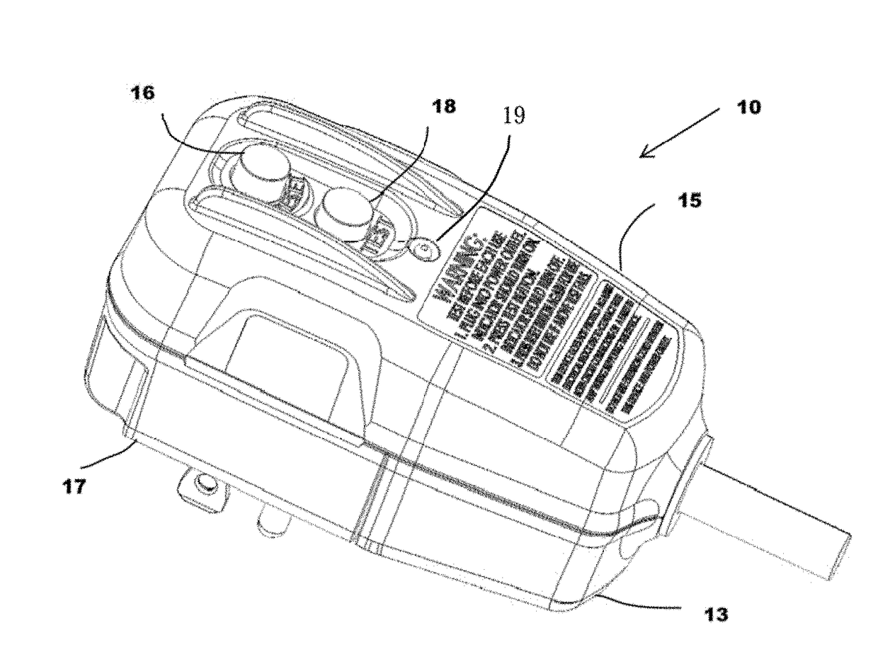
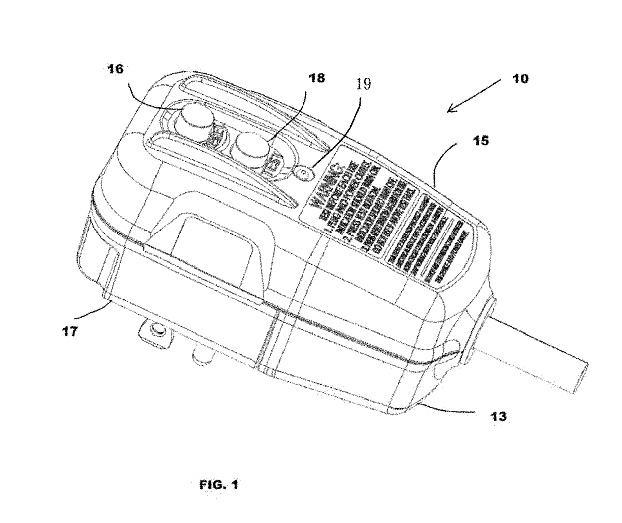
[0013]In accordance with one embodiment of the present invention an electronic circuit (EC) housing is provided. The EC housing includes a printed circuit board (PCB) chamber and a cable chamber isolated from the PCB chamber. The overall length of the electronic circuit housing is less than or equal to 3.95 inches, and the volume of the PCB chamber is substantially equal to 9.25 cubic inches. The internal volume of the cable chamber is substantially equal to 7.35 cubic inches, and the ratio of the PCB chamber volume to the cable chamber volume is substantially constant at 1.26.
[0014]The invention is also directed towards a water-resistant ground fault interrupter circuit (GFCI) housing. The housing includes a top housing cover having a length L1 and a groove circumscribing the top housing. The housing also includes a bottom housing cover mateable with the top housing cover and having a length L2, wherein L2 is substantially 2.2 inches. The bottom housing also includes a first compression ridge disposed along the top housing mating surfaces. The bottom housing cover also includes a second groove disposed along the bottom cable cover mating surface. Also included is a bottom cable cover mateable with the top housing cover and the bottom housing cover. The bottom cable cover has a length L3, wherein L3 is less than or equal to 1.75 inches. Overall, L2+L3=L1. The bottom cable cover also includes a second compression ridge disposed the top housing mating surfaces (i.e., the edge of the bottom cable cover that is mateable with the top housing). The bottom cable cover includes a third compression ridge disposed along the bottom housing mating surface.

Problems solved by technology

On occasion, the electrical system may experience a ground fault condition while the load is connected to the power supply.
Often a ground fault will occur if the hot line becomes inadvertently grounded.
A ground fault condition can result in a loss of power to the electrical appliance because current is unable to flow to the load.
As a consequence, an excessive amount of current tends to flow into the ground conductor of the electrical system which, in turn, creates dangerous voltage levels at points in the circuit that should be at ground potential.
This condition can result in potentially dangerous electrical shocks, which could seriously injure an individual.
However, disassembly of the housing usually exposes the GFCI or ALCI circuitry to potential damage which may not be discovered until operation, leading to potentially catastrophic damage and / or injury.
Furthermore, the GFCI and / or ALCI circuits are susceptible to moisture damage.
Where the terminal block and the circuitry share a common space, as in the prior art, moisture seepage into the common space may cause unknown circuitry damage to the GFCI tripping circuit and / or hardware leading to potentially catastrophic damage and / or injury.
One disadvantage is that a gap between the test button and a housing of the circuit breaker is present before or during when the button is depressed.
When the gap between the button and the housing is present, several concerns arise related to moisture, corrosion, and potential electric shock.
Although PCB's are typically conformal coated, this does not guarantee that moisture could not damage the PCB and / or related electrical components and disable the push to test button and / or present the possibility of the a user being exposed to electrical shock.

Method used


Image

  • Multi-Chamber GFCI Housing Apparatus
  • Multi-Chamber GFCI Housing Apparatus
  • Multi-Chamber GFCI Housing Apparatus

Examples


Embodiment Construction

[0029]The following brief definition of terms shall apply throughout the application:

[0030]The term “comprising” means including but not limited to, and should be interpreted in the manner it is typically used in the patent context;

[0031]The phrases “in one embodiment,”“according to one embodiment,” and the like generally mean that the particular feature, structure, or characteristic following the phrase may be included in at least one embodiment of the present invention, and may be included in more than one embodiment of the present invention (importantly, such phrases do not necessarily refer to the same embodiment);

[0032]If the specification describes something as “exemplary” or an “example,” it should be understood that refers to a non-exclusive example; and

[0033]If the specification states a component or feature “may,”“can,”“could,”“should,”“preferably,”“possibly,”“typically,”“optionally,”“for example,” or “might” (or other such language) be included or have a characteristic, t...


PUM


Abstract

In accordance with one embodiment of the present invention a multi-chamber GFCI housing apparatus is provided. The multi-chamber GFCI housing includes a printed circuit board (PCB) chamber and an isolated cable chamber; each chamber is independently accessible and water resistant. In addition, the relative volumes of each independent chamber permit sufficient housing volume to allow for sufficient spacing between electrical GFCI components and electrical PCB traces to prevent the risk of arcing between the components while also adhering to constrained dimensions according to electrical codes and standards.

Description

1. FIELD OF USE[0001]The present invention relates generally to ground fault safety devices and more specifically to circuit interrupter enclosures.2. DESCRIPTION OF PRIOR ART (BACKGROUND)[0002]It is well known for electrical appliances, such as hair dryers, to draw electrical power through connection to a power source, such as an electrical outlet. Specifically, the electrical appliance (which serves as the load of the electrical system) is connected to the power source by a pair of current-carrying wires. The pair of current-carrying wires typically include a hot wire and a neutral wire, the pair of wires having equal but opposite magnitudes under normal conditions.[0003]On occasion, the electrical system may experience a ground fault condition while the load is connected to the power supply. A ground fault condition occurs when the differential between the values of the currents of the two wires exceeds a predetermined value. Often a ground fault will occur if the hot line become...

Claims


Application Information

Patent Timeline
Patent Type & Authority Applications(United States)
IPC IPC(8): H05K5/00H01R9/24H01R4/34H01R24/30H01H13/06H01H13/14H02H3/16H05K5/03
CPCH05K5/0047H01R9/2425H01R9/2491H01R4/34H01R2103/00H01H13/06H01H13/14H02H3/16H05K5/03H01R24/30H01R13/5202H01R13/6658H01R13/7135H01R24/68
Inventor AROMIN, VICTOR V.PAQUETTE, DANIEL R.
Owner TOWER MFG
Why Eureka
Try Eureka