
Dynamic stabilization connecting member with pre-tensioned solid core

a technology of dynamic stabilization and connecting members, applied in the direction of internal osteosynthesis, internal osteosynthesis, osteosythesis devices, etc., can solve the problems that the cords or strands utilized in such systems do not allow for elastic distraction of the system, and achieve the effect of reducing volume, low profile and convenient us

Active Publication Date: 2018-08-09
JACKSON
View PDF3 Cites 10 Cited by
  • Summary
  • Abstract
  • Description
  • Claims
  • Application Information

AI Technical Summary

Benefits of technology

The invention provides a medical implant assembly that allows for dynamic and protected motion of the spine. The assembly includes a longitudinal connecting member with an inner pre-tensioned core and an outer sleeve that is in slidable relationship with the core. The assembly also includes at least two bone anchor attachment structures, an anchor member portion, a pre-tensioned bendable core extension, and a fixation structure. The technical effects of the invention include improved spinal mobility, reduced risk of complications, and improved patient outcomes.

Problems solved by technology

Although flexible, the cords or strands utilized in such systems do not allow for elastic distraction of the system once implanted because the cord or strand must be stretched or pulled to maximum tension in order to provide a stable, supportive system.
The complex dynamic conditions associated with spinal movement create challenges for the design of elongate elastic longitudinal connecting members that exhibit an adequate fatigue strength to provide stabilization and protected motion of the spine, without fusion, and that allow for some natural movement of the portion of the spine being reinforced and supported by the elongate elastic or flexible connecting member.
A further challenge are situations in which a portion or length of the spine requires a more rigid stabilization, possibly including fusion, while another portion or length may be better supported by a more dynamic system that allows for protective movement.

Method used


Image

  • Dynamic stabilization connecting member with pre-tensioned solid core
  • Dynamic stabilization connecting member with pre-tensioned solid core
  • Dynamic stabilization connecting member with pre-tensioned solid core

Examples


third embodiment

[0095]With reference to FIG. 18, a dynamic longitudinal connecting member assembly, generally 301 is illustrated. The assembly 301 includes an anchor member 304 having an inner core 306 and a bone anchor attachment portion 308; a spacer 310, a sleeve 316, a bumper 318 and a crimping ring 320. The illustrated spacer 310, sleeve 316, bumper 318 and crimping ring 320 are identical to the spacer 210, sleeve 216, bumper 218 and crimping ring 220 previously described herein with respect to the assembly 201. The anchor member 304 is identical to the anchor member 204 with the exception that the bone anchor attachment portion 308 is of a length to receive three bone screw receivers 31 therealong while the portion 208 is sized to receive two bone screw receivers 31. It is foreseen that longitudinal connecting member assemblies according to the invention may be of a variety of lengths for cooperation with a plurality of bone screws 25, either along a rigid end portion, such as the portion 308...

embodiment 401

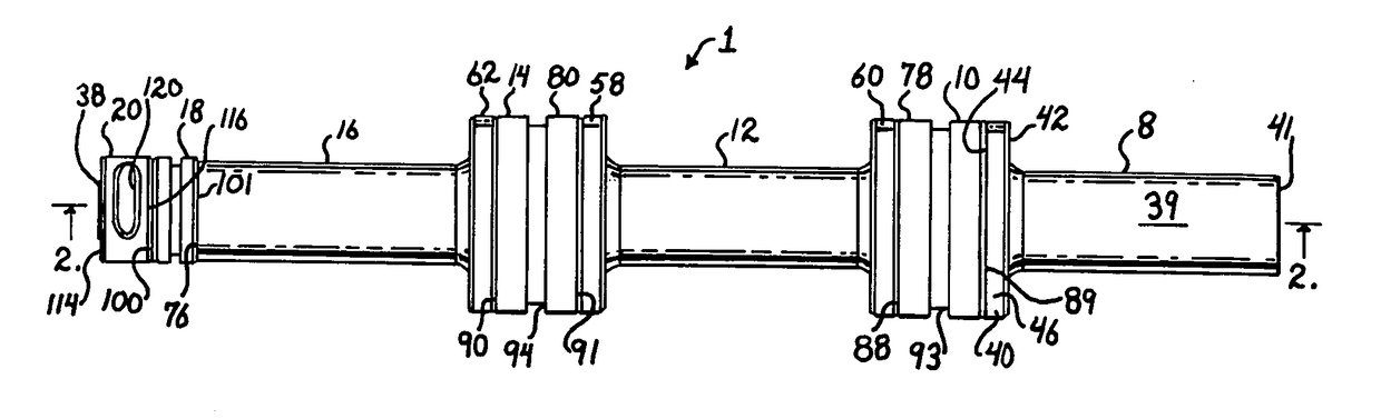
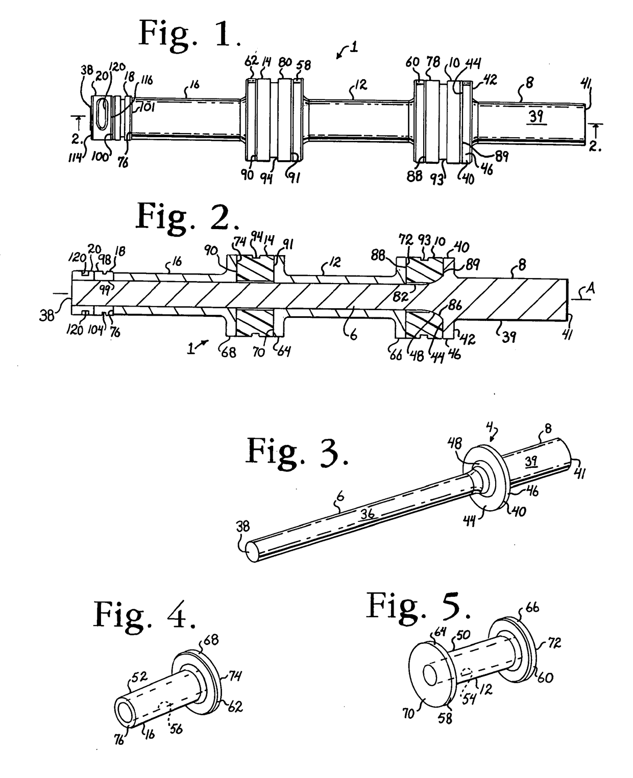
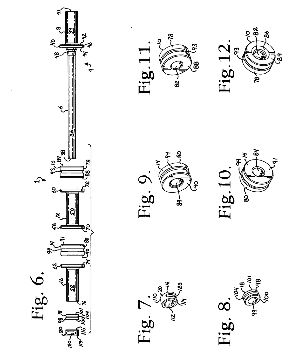
[0098]With reference to FIGS. 21-23, another embodiment of a connecting member according to the invention, an assembly 401 is shown that includes the same or similar components to the assemblies 1 and 201, for example, previously described herein. However, the components are sized such that the resulting assembly 401 has a constant outer diameter along an entire length thereof. Thus, the assembly 401 generally designates a non-fusion dynamic stabilization longitudinal connecting member assembly according to the present invention having an anchor member, generally 404, that includes an elongate segment or inner core 406 integral with or otherwise fixed to a bone anchor attachment portion 408; an end spacer or stop 410; a second elastic spacer 411; a rigid sleeve 412; and a crimping ring 420; all substantially symmetrically aligned with respect to a central axis of the anchor member 404. The elongate core 406 of the anchor member 404 is receivable within the spacers 410 and 411, the s...


PUM


Abstract

A dynamic longitudinal connecting member assembly includes an anchor member having an integral or otherwise fixed elongate core of circular or non-circular cross-section. The core is pre-tensioned and extends through at least one elastic spacer and at least one outer sleeve. The anchor member and the outer sleeve each attach to at least one bone anchor. In operation, the core is held in tension by the spacer.

Description

CROSS-REFERENCE TO RELATED APPLICATIONS[0001]This application is a continuation of U.S. application Ser. No. 15 / 197,247, filed on Jun. 29, 2016, which is a continuation of U.S. application Ser. No. 13 / 317,158, filed on Oct. 11, 2011, now abandoned, which is a continuation of U.S. application Ser. No. 12 / 459,492, filed Jul. 1, 2009, now U.S. Pat. No. 8,366,745. U.S. application Ser. No. 12 / 459,492 claims the benefit of U.S. Provisional Application No. 61 / 137,743, filed Aug. 1, 2008 and U.S. Provisional Application No. 61 / 134,480, filed Jul. 10, 2008. U.S. application Ser. No. 12 / 459,492 is a continuation-in-part of U.S. application Ser. No. 12 / 156,260, filed May 30, 2008, now U.S. Pat. No. 7,951,170, which claims the benefit of U.S. Provisional Application No. 60 / 994,068, filed Sep. 17, 2007, and U.S. Provisional Application No. 60 / 932,567, filed May 31, 2007. U.S. application Ser. No. 12 / 459,492 is also a continuation-in-part of U.S. application Ser. No. 12 / 148,465, filed Apr. 18, 2...

Claims


Application Information

Patent Timeline
Patent Type & Authority Applications(United States)
IPC IPC(8): A61B17/70
CPCA61B17/702A61B17/7037A61B17/7049A61B17/7026A61B17/705A61B17/7004A61B17/7031A61B17/7011A61B17/701A61B17/7008A61B17/7025A61B17/7035
Inventor JACKSON, ROGER P.
Owner JACKSON
Features
  • Generate Ideas
  • Intellectual Property
  • Life Sciences
  • Materials
  • Tech Scout
  • Unparalleled Data Quality
  • Higher Quality Content
  • 60% Fewer Hallucinations
Learn More