Elongate printhead having robust electrical assembly

a printhead and electrical assembly technology, applied in the direction of printing, power drive mechanisms, inking apparatus, etc., can solve the problems of lcp manifolds with some practical limitations, chip depriming, and labyrinthine ink pathways that are susceptible to trapping, and achieve the effect of facilitating temperature regulation of respective printhead chips

Active Publication Date: 2018-08-09
MEMJET TECH LTD
View PDF0 Cites 1 Cited by
  • Summary
  • Abstract
  • Description
  • Claims
  • Application Information

AI Technical Summary

Benefits of technology

[0014]The printhead according to the first aspect advantageously enables printing of four colors of ink (e.g. CMYK) from a single replaceable printhead, whilst simplifying printhead plumbing and alignment issues. In particular, a multi-channeled printhead chip may be plumbed for printing two ink colors only and the printhead chips are attached to a common surface of the manifold in, for example, two parallel rows to allow printing of all four ink colors. By arranging two rows of printheads chips on a single replaceable manifold, the precise alignment of the chips can be performed with high accuracy at the factory rather than in the field by a user or technician. Moreover, since each printhead chip is configured for printing 4 or more (e.g. 4, 5, 6 or 7) ink channels, then each color has redundancy which increases print speed and / or minimizes print artifacts caused by dead nozzles. In the case of a Memjet® printhead chip having 5 ink channels, the center channel may be inoperative to provide 2 ink channels for each color. This arrangement advantageously increases the distance between color channels printing different colors, thereby minimizing color mixing on the nozzle plate of the printhead chip. In other words, the printhead according to the first aspect provides an excellent compromise between the demands of print speed, redundancy, printhead alignment and color mixing on the nozzle plate.
[0159]Preferably, the inkjet nozzle devices are thermally-actuated devices, such that, in use, the dummy color channel facilitates temperature regulation of a respective printhead chip via actuation of the inkjet devices in the dummy color channel.

Problems solved by technology

However, at high print speeds, the LCP manifold has some practical limitations.
Without a sufficiently large body of ink close to the printhead chips, the chips may become starved of ink under periods of high ink demand and lead to chip de-priming.
Secondly, the labyrinthine ink pathways are susceptible to trapping air bubbles; if an air bubble becomes trapped in the system, the printhead chips will become starved of ink and de-prime.
Whilst LCP is a satisfactory choice of material for A4 printheads, having a CTE similar to silicon, it typically lacks the required rigidity to manufacture longer printheads (e.g. A3 printheads).
However, flex PCBs are expensive and add significantly to manufacturing costs.
Moreover, bending of a flex PCB through a tight angle places strain on the PCB and limits the components that may be incorporated thereon.
However, a problem with stacking printheads in this manner is that precise registration of the printheads is required when printheads are replaced by the user.
Further, there are high demands on media feed mechanisms, which must maintain alignment of the print media with the printheads through a relatively long print zone.

Method used


Image

  • Elongate printhead having robust electrical assembly
  • Elongate printhead having robust electrical assembly
  • Elongate printhead having robust electrical assembly

Examples


Embodiment Construction

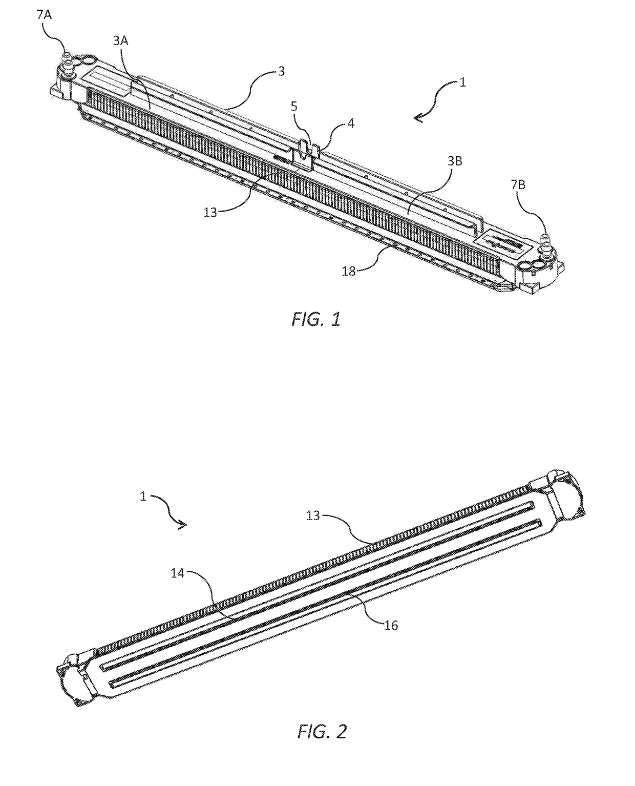
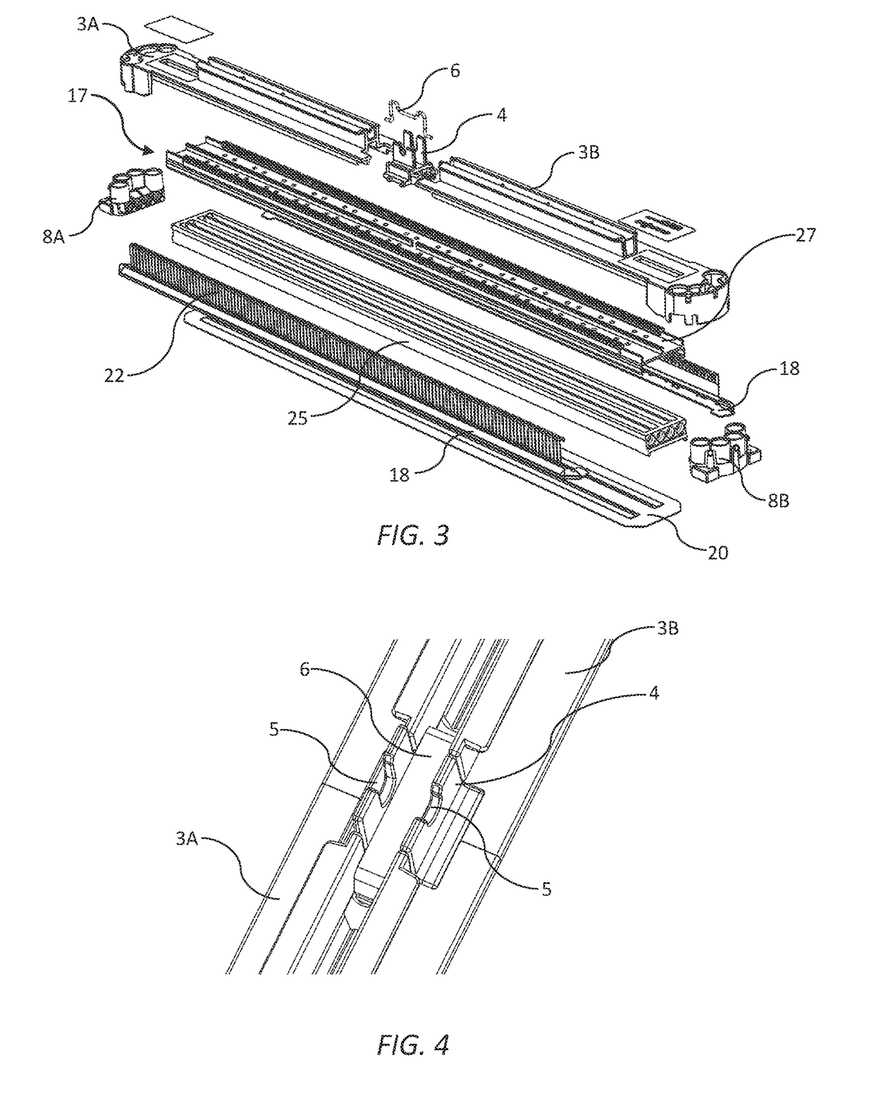
[0186]Referring to FIGS. 1 to 4, there is shown an inkjet printhead 1 in the form of a replaceable printhead cartridge for user insertion in a printer (not shown). The printhead 1 comprises an elongate molded plastics casing 3 having a first casing part 3A and a second casing part 3B positioned at either side of a central locator 4. The central locator 4 has an alignment notch 5 for positioning the printhead cartridge 1 relative to a print module, such as a print module of the type described in US2017 / 0313061, the contents of which are incorporated herein by reference. The first and second casing parts 3A and 3B are biased towards each other and the central locator 4 by means of a spring clip 6 engaged between the first and second casing parts (see FIG. 4). The two-part casing 3 in combination with the spring clip 6 enables the casing to expand longitudinally, at least to some extent, to accommodate a degree of longitudinal expansion in a main body 17 of the printhead 1. This arrang...


PUM


Abstract

An inkjet printhead includes: a rigid elongate carrier having an ink supply channel and a lower surface having a plurality of printhead chips mounted thereon; a rigid PCB attached to the lower surface of the carrier, the PCB extending a length of the carrier and projecting laterally beyond a sidewall of the carrier; a lead retainer attached to the sidewall of the carrier; and a plurality of leads extending upwardly from contact pads positioned along a longitudinal edge portion of the PCB, each lead being secured to the sidewall of the carrier via the lead retainer. The PCB supplies power and data to the printhead chips via electrical connections between the PCB and the printhead chips.

Description

CROSS-REFERENCE TO RELATED APPLICATIONS[0001]The present application claims the benefit of priority under 35 U.S.C. § 119(e) of U.S. Provisional Application Ser. No. 62 / 455,346, entitled INKJET PRINTHEAD SUITABLE FOR FULL COLOR PAGEWIDE PRINTING, filed Feb. 6, 2017, the content of which is hereby incorporated by reference in its entirety for all purposes.FIELD OF THE INVENTION[0002]This invention relates to an inkjet printhead. It has been developed primarily to provide a robust full-color printhead suitable for high-speed pagewide printing.BACKGROUND OF THE INVENTION[0003]The Applicant has developed a range of Memjet® inkjet printers as described in, for example, WO2011 / 143700, WO2011 / 143699 and WO2009 / 089567, the contents of which are herein incorporated by reference. Memjet® printers employ one or more stationary inkjet printheads in combination with a feed mechanism which feeds print media past the printhead in a single pass. Memjet® printers therefore provide much higher printi...

Claims


Application Information

Patent Timeline
Patent Type & Authority Applications(United States)
IPC IPC(8): B41J2/14
CPCB41J2/1433B41J2002/14491B41J2/14B41J2002/14362B41J2202/20B41J2202/21B41J2002/14419B41J2/14145B41J2202/19B41J2/155B41J2/2103B41J2/1752B41J2/19B41J2/21B41J25/34B41J2/17523B41J2/175
Inventor THELANDER, JASONBURKE, DAVIDTHOMAS, ANDREW
Owner MEMJET TECH LTD
Why Eureka
Try Eureka