Rotational joint for an aircraft folding wing

a technology for folding wings and rotational joints, which is applied in the direction of fuselages, wing adjustments, drag reduction, etc., can solve the problems of relatively complex design and construction of folding wings, effective maximum aircraft span, etc., and achieves the effect of reducing the concentration of loading on the locking pin, reducing the backlash of the rotational joint under loading, and avoiding large stresses

Active Publication Date: 2018-08-09
AIRBUS OPERATIONS LTD
View PDF0 Cites 8 Cited by
  • Summary
  • Abstract
  • Description
  • Claims
  • Application Information

AI Technical Summary

Benefits of technology

[0007]This is advantageous in that the alignment mechanism may allow for the locking bore to be accurately aligned with the locking pin, despite any tolerances and/or elasticity in the rotational joint (or in the aircraft generally). This may allow the locking pin to form a close-fit with the locking bore, which reduces concentrated loading on the locking pin and reduces backlash in the rotational joint under loading.
[0008]Furthermore, the alignment mechanism provides this alignment function separat

Problems solved by technology

However, the maximum aircraft span is effectively limited by airport operating rules which govern various clearances required when maneuvering around the airport (such as the span a

Method used


Image

  • Rotational joint for an aircraft folding wing
  • Rotational joint for an aircraft folding wing
  • Rotational joint for an aircraft folding wing

Examples


first embodiment

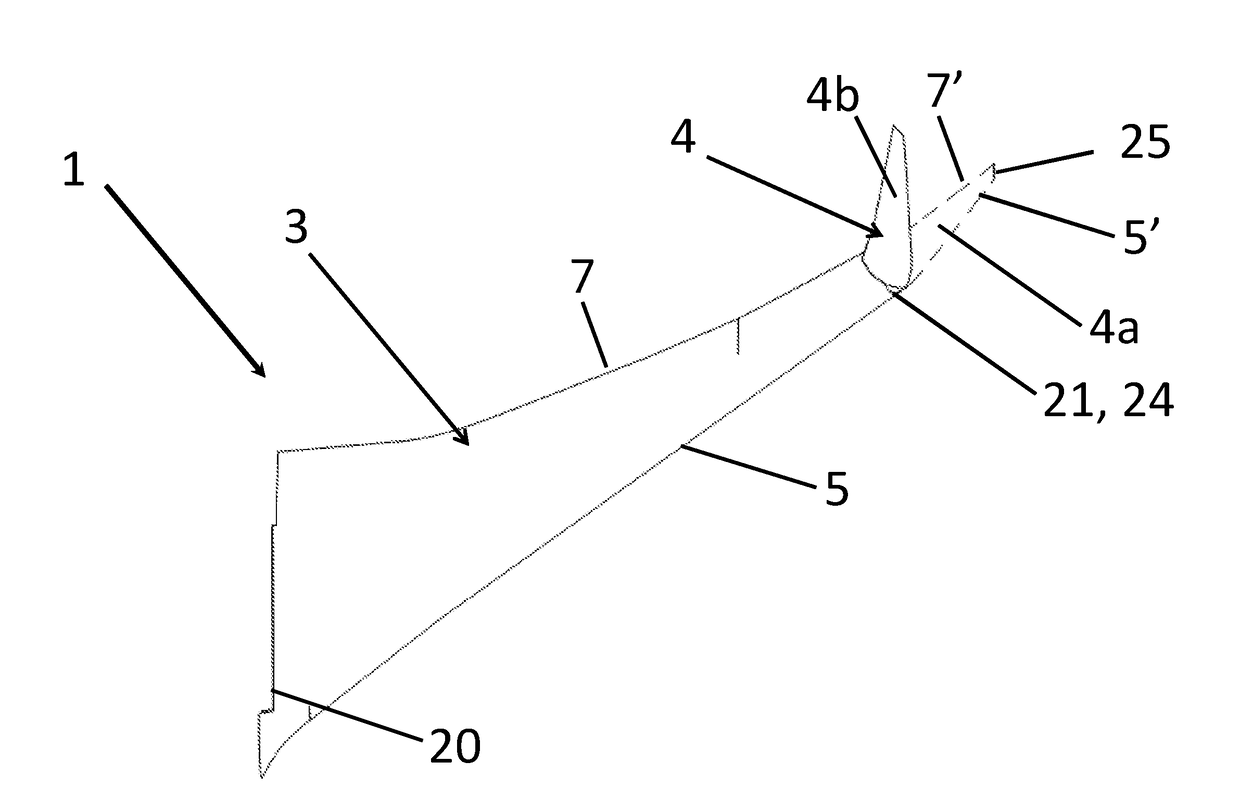
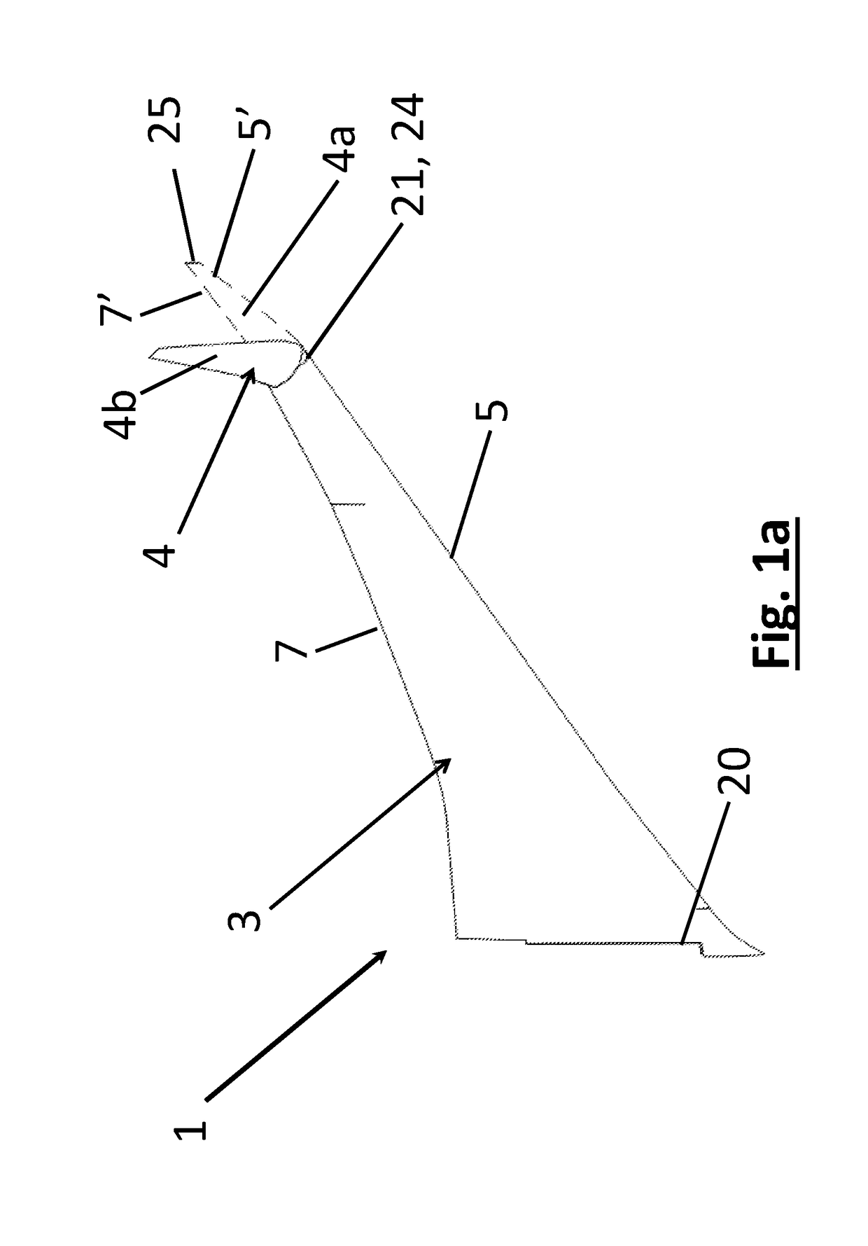
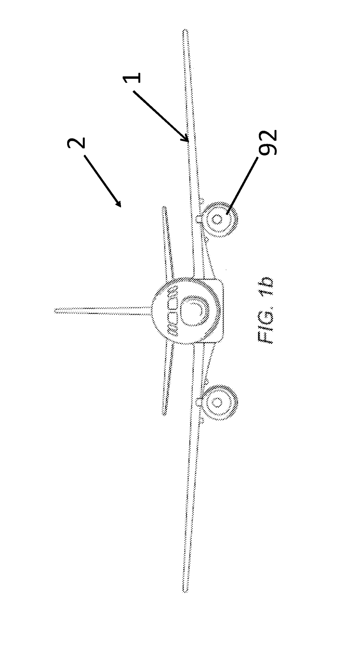
[0166]FIG. 1a is a perspective view of an aircraft wing 1 of an aircraft 2 according to the invention. The aircraft wing 1 comprises a fixed wing 3 and a wing tip device 4.

[0167]The aircraft 2 is a passenger aircraft comprising a passenger cabin comprising a plurality of rows and columns of seat units for accommodating a multiplicity of passengers, in this case more than 50 passengers. The aircraft is a powered aircraft and comprises engines 92, mounted under the wings 1, for propelling the aircraft 2.

[0168]The fixed wing 3 extends outboard from the fuselage of the aircraft, in a span wise direction from a root 20 to a tip 21. The fixed wing 3 also extends in a chord-wise direction from a leading edge 5 to a trailing edge 7.

[0169]The wing tip device 4 is located at the outboard tip 21 of the fixed wing 3. In the described embodiment the wing tip device 4 is in the form of a planar wing tip extension, although the invention is also applicable to other types of wing tip device (e.g. a...

fourth embodiment

[0289]This embodiment differs from the fourth embodiment in that a jamming sensor, in the form of a magnetic sensor 203, is fixedly attached to the bore housing 50 and faces into the cylindrical bore 49 in which the alignment pin 61 is slidably mounted. A magnet 204 is fixedly attached to the alignment pin 61, so that it moves with the alignment pin 61 in the first direction D1.

[0290]The magnetic sensor 203, and magnet 204, form part of the control system 305. The magnetic sensor 203 is connected to the control unit 200, to provide an input signal to the control unit 200 (the control unit 200 is schematically shown twice in FIG. 14a for illustrative purposes, but it will be appreciated that there is only one control unit 200), and is arranged to sense the position of the magnet 204 in order to detect whether or not the alignment pin 61 has passed to its end position in the alignment bore 62. The control system 305, including the control unit 200, the solenoids 82, 87 and the operato...


PUM


Abstract

An aircraft (2) including a wing (1), the wing (1) having a fixed wing (3) and a wing tip device (4) at the tip of the fixed wing (3), the wing tip device (4) being rotatable relative to the fixed wing (3) between flight and ground configurations, the aircraft including a rotational joint (10) with a rotation mechanism (11) that rotatably couples the wing tip device (4) to the fixed wing (3) and a locking mechanism including a locking bore (53, 54) and a locking pin (51) that is receivable in the locking bore to lock the wing tip device (4) in one of the flight or ground configurations, wherein the rotational joint includes an alignment mechanism including an alignment pin (61) and an alignment bore (62, 63) and at least one of the alignment pin and alignment bore is tapered such that engagement of the alignment pin (61) in the alignment bore acts to guide the locking bore and locking pin into alignment.

Description

RELATED APPLICATION[0001]This application claims priority to United Kingdom (GB) patent application 1701850.8 filed Feb. 3, 2017, the entirety of which is incorporated by reference.BACKGROUND OF THE INVENTION[0002]The present invention relates to aircraft comprising foldable wings, and to rotational joints for use on such aircraft.[0003]There is a trend towards increasingly large passenger aircraft with higher performance efficiency (for example fuel burn reduction), for which it is desirable to have correspondingly large wing spans. However, the maximum aircraft span is effectively limited by airport operating rules which govern various clearances required when maneuvering around the airport (such as the span and / or ground clearance required for gate entry and safe taxiway usage).[0004]In some suggested designs aircraft are provided with wings which may have wing tips that are foldable to reduce the span of the aircraft on the ground (compared to when the aircraft is configured for...

Claims


Application Information

Patent Timeline
IPC IPC(8): B64C3/56
CPCB64C3/56B64C1/30B64C3/00B64D47/00Y02T50/10
Inventor BRAKES, DAVID
Owner AIRBUS OPERATIONS LTD
Why Eureka
Try Eureka