Image forming device

a technology of forming device and transfer belt, which is applied in the direction of gearing details, mechanical equipment, machines/engines, etc., can solve the problems of excessive load on the driving source, reducing the transfer speed advancing wear of the transfer belt, so as to reduce the sliding resistance

Active Publication Date: 2018-08-16
RISO KAGAKU CORP
View PDF2 Cites 3 Cited by
  • Summary
  • Abstract
  • Description
  • Claims
  • Application Information

AI Technical Summary

Benefits of technology

[0006]The present invention is to further improve the aforementioned past proposal, and an object of the present invention is to provide an image forming device which can reduce the sliding resistan

Problems solved by technology

Incidentally, if the transfer belt and the platen plate are brought into sliding contact with each other by a foreign substance or the like having entered in a gap between the both, it is concerned that wear of the transfer

Method used


Image

  • Image forming device
  • Image forming device
  • Image forming device

Examples


Embodiment Construction

[0022]An inkjet printer according to an embodiment of the present invention will be described below with reference to the drawings.

[Constitution of Inkjet Printer]

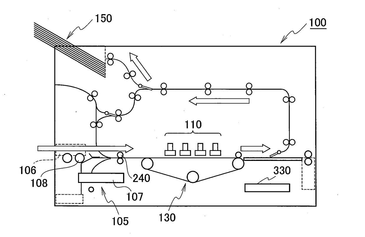
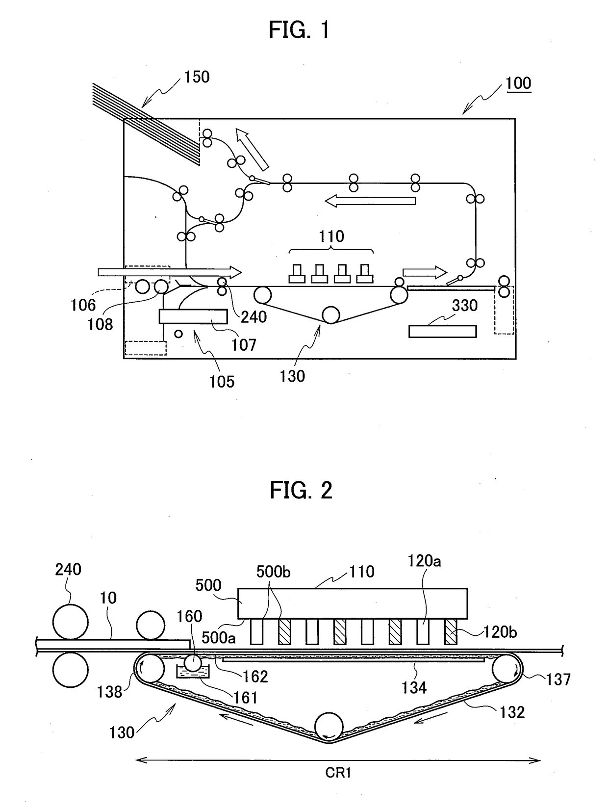
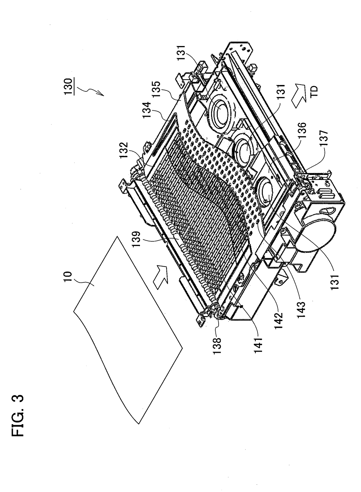
[0023]FIG. 1 is an outline sectional view illustrating an internal constitution of an inkjet printer according to an embodiment of the present invention. FIG. 2 is an explanatory view of an image forming path where image forming in FIG. 1 is performed, illustrated from a side. Further, FIG. 3 is a partially cutaway perspective view illustrating a sheet transfer unit in FIG. 2. FIG. 4A is an enlarged plan view of an essential part of an example of a constitution of a platen plate in FIG. 3. FIG. 4B is a partially cutaway enlarged perspective view of a portion in the essential part of the example of the constitution of the platen plate in FIG. 3. FIG. 4C is an enlarged side view of the essential part of an example of the constitution of the platen plate in FIG. 3. FIG. 5 is an enlarged side sectional view of a portion of the...


PUM


Abstract

As a lubricant present between a transfer belt for transferring a print sheet and a platen plate on a rear side thereof and bringing the both into close contact, a lubricant containing 70 weight % or more of a fatty acid ester solvent with carbon number in a molecule of 20 or more and 34 or less is used so as to reduce sliding between the transfer belt and the platen plate and sliding resistance generated between the transfer belt for transferring the print sheet and an auxiliary plate arranged along this.

Description

BACKGROUND1. Technical Field[0001]The present invention relates to an image forming device in which a print sheet is transferred by a transfer belt in a paper feed / discharge process of a print sheet to / from a printing unit and a print process or the like in the printing unit.2. Related Art[0002]In an inkjet printer, for example, a print sheet fed from a paper feed tray is transferred by an endless transfer belt extended between a driving roller and a driven roller. Then, an image is formed (printed) on a print sheet being transferred by the ink ejected from a nozzle of an inkjet head arranged by facing the transfer belt.[0003]On a rear side of a portion in the transfer belt faced with the inkjet head, a flat-plate shaped platen plate is arranged in proximity to a rear surface of the transfer belt. By the presence of this platen plate, a portion of the print sheet on the transfer belt faced with the inkjet head can be held flatly, and a head gap can be kept at a predetermined interva...

Claims


Application Information

Patent Timeline
IPC IPC(8): B41J2/21B41J11/02B41J11/00
CPCB41J2/2103B41J11/02B41J11/007B41J11/06B41J11/0085B41J2/1714F16H57/045F16H57/04F16H57/0434F01D25/18F01M9/12C10N2040/00C10N2040/02C10N2040/06C10N2040/38
Inventor ENDO, TOSHIHIRO
Owner RISO KAGAKU CORP
Why Eureka
Try Eureka