Electric vehicle power system with shared converter

a technology of electric vehicles and converters, applied in the direction of dynamo-electric converter control, process and machine control, instruments, etc., can solve the problems of increasing equipment malfunctions or failures, occupying more space than necessary, and adding weight, so as to facilitate battery charging and facilitate battery discharging. , the effect of facilitating the battery charging

Active Publication Date: 2018-08-16
TOYOTA JIDOSHA KK
View PDF17 Cites 20 Cited by
  • Summary
  • Abstract
  • Description
  • Claims
  • Application Information

AI Technical Summary

Benefits of technology

[0004]What is described is a system for an electric vehicle in a grid-connected mode or in a stand-alone mode. The system includes a battery control unit configured to be in the grid-connected mode or the stand-alone mode based on operation of the electric vehicle. The system also includes a shared boost converter connected to a battery. The shared boost converter is configured to receive power from an alternating current (AC) power source, step up voltage and convert the received AC power to direct current (DC) power, and output converted and stepped up DC power for storage in the battery when the battery control unit is in the grid-connected mode. The shared boost converter is also configured to receive DC power from the battery, step up voltage of the received DC power, and output stepped up DC power when the battery control unit is in the stand-alone mode. The system also includes an inverter connected to the shared boost converter and configured to receive the stepped up DC power from the shared boost converter when the battery control unit is in the stand-alone mode, convert the received stepped up DC power to AC power, and output converted AC power. The system also includes a motor / generator connected to the inverter and configured to receive the converted AC power for powering a drivetrain of the electric vehicle.
[0005]Also described is a system for an electric vehicle. The system includes a battery control unit configured to be in a grid-connected mode or a stand-alone mode based on operation of the electric vehicle. The system also includes a shared boost converter connected to a battery. The shared boost converter is configured to facilitate charging of the battery when the battery control unit is in the grid-connected mode by receiving power from an alternating current (AC) power source, stepping up voltage and converting the received AC power to direct current (DC) power, and outputting converted and stepped up DC power for storage in the battery. The shared boost converter is also configured to facilitate charging of the battery when the battery control unit is in the stand-alone mode by receiving generated DC power, stepping down voltage of the generated DC power, and outputting the stepped down DC power for storage in the battery. The shared boost converter is also configured to facilitate discharging of the battery when the battery control unit is in the grid-connected mode by receiving stored DC power from the battery, stepping down voltage and converting the received stored DC power into AC power, and outputting the stepped down and converted AC power for providing to the AC power source. The shared boost converter is also configured to facilitate discharging of the battery when the battery control unit is in the stand-alone mode by receiving DC power from the battery, stepping up voltage of the received DC power, and outputting stepped up DC power for powering a motor / generator of the electric vehicle.
[0006]Also described is an electric vehicle. The electric vehicle is connected to an AC power source in a grid-connected mode and disconnected from the AC power source in a stand-alone mode. The electric vehicle includes a battery control unit configured to be in the grid-connected mode or the stand-alone mode. The electric vehicle includes a shared boost converter. The shared boost converter is configured to step up voltage or step down voltage, and convert AC power to DC power or convert DC power to AC power when the battery control unit is in the grid-connected mode. The shared boost converter is also configured to step up voltage or step down voltage when the battery control unit is in the stand-alone mode. The electric vehicle also includes an inverter connected to the shared boost converter and configured to convert AC power to DC power or convert DC power to AC power when the battery control unit is in the stand-alone mode. The electric vehicle also includes a motor / generator connected to the inverter and configured to receive AC power from the battery via the inverter for powering a drivetrain of the electric vehicle or generate AC power for charging the battery.

Problems solved by technology

A drawback of these conventional systems has been that they occupy more space than necessary, adding weight, inefficiency, and additional opportunities for malfunctioning or failing of equipment.

Method used


Image

  • Electric vehicle power system with shared converter
  • Electric vehicle power system with shared converter
  • Electric vehicle power system with shared converter

Examples


Embodiment Construction

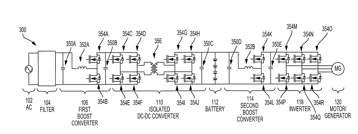
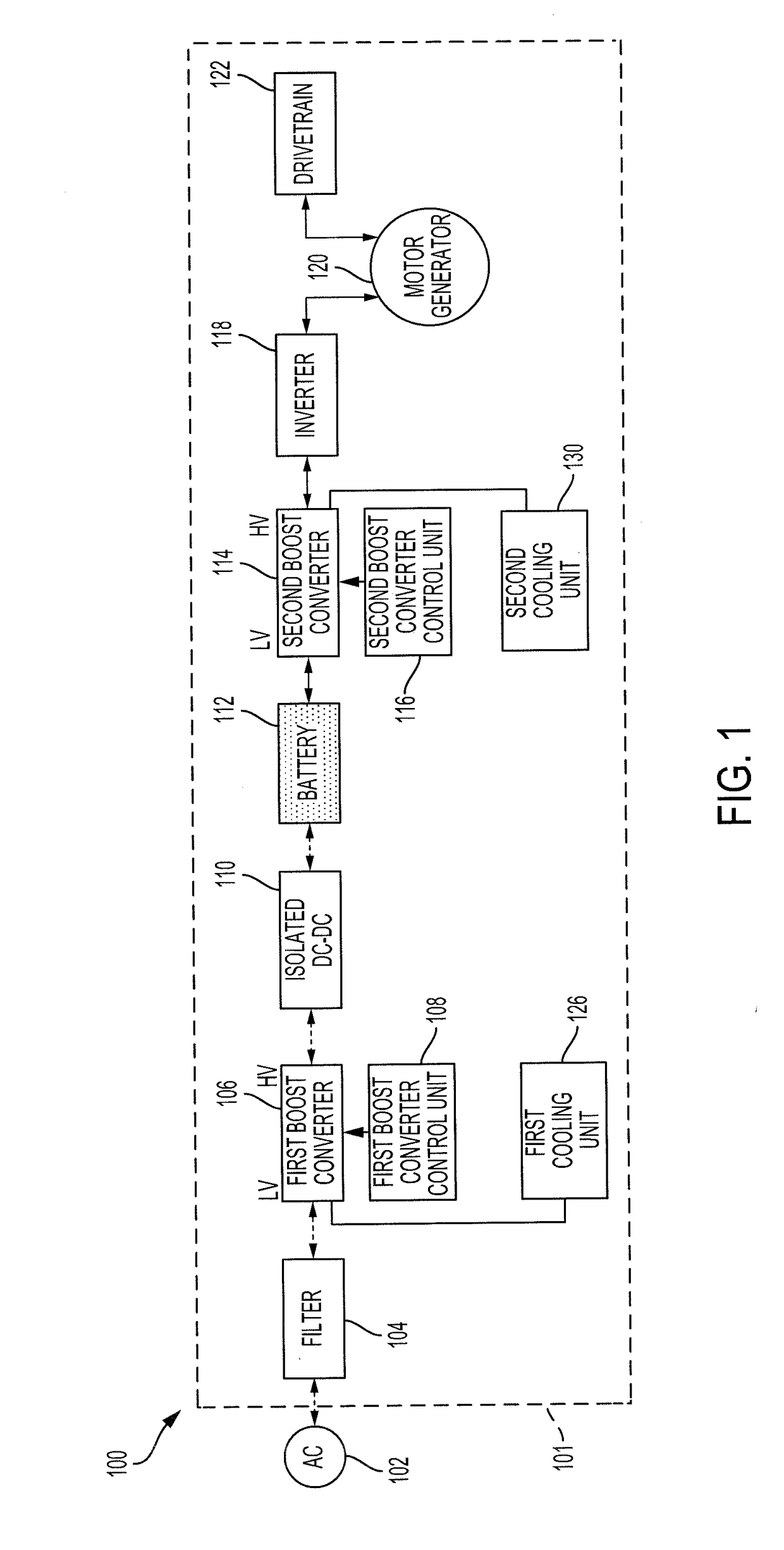
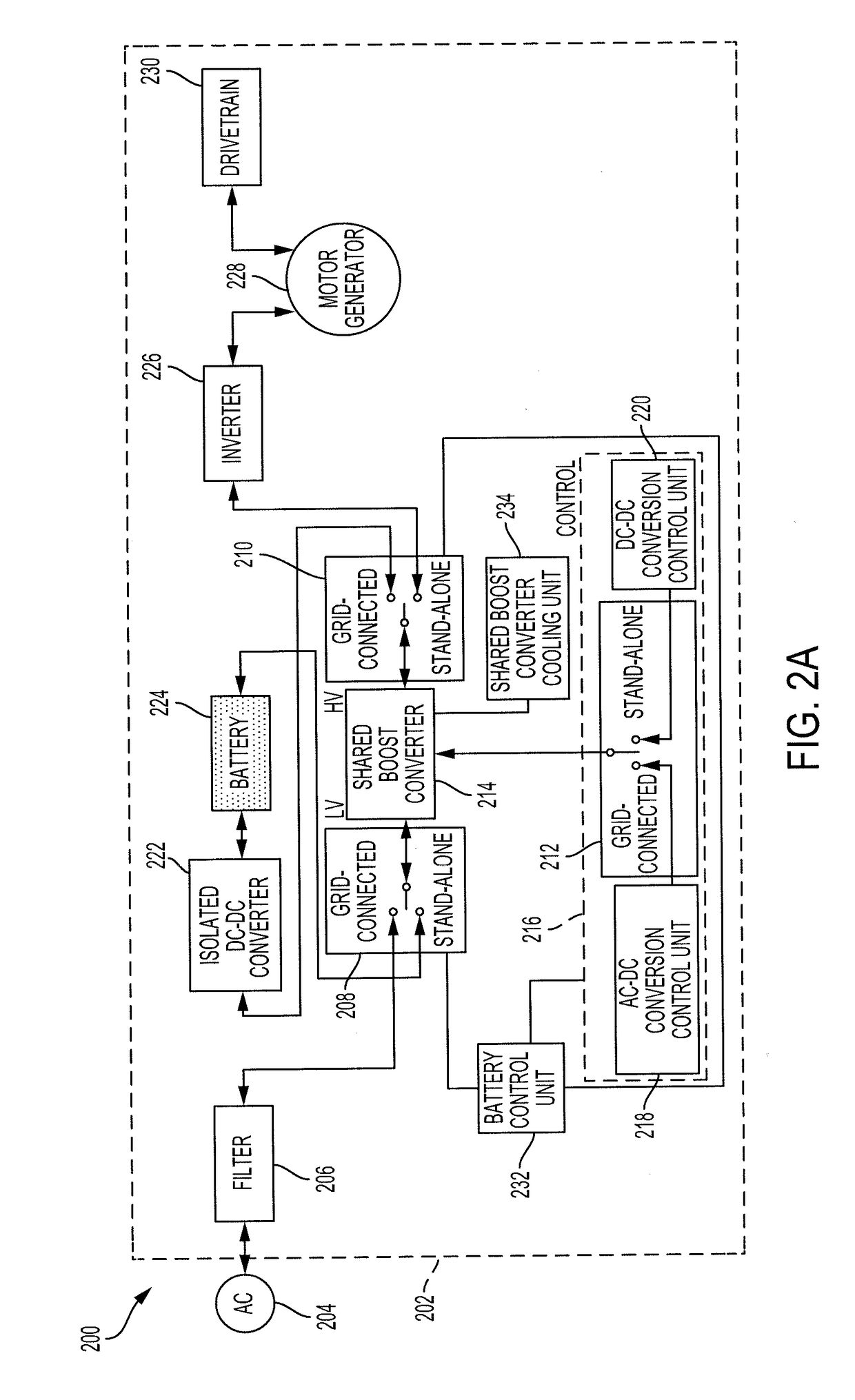
[0014]Disclosed herein are systems, vehicles and methods for charging and discharging a battery of an electric vehicle in a grid-connected mode or in a stand-alone mode. Power conversion systems for electric vehicles may operate in one of two modes, a grid-connected mode or a stand-alone mode. When in the grid-connected mode, the electric vehicle may be stationary and connected to a power source. In the grid-connected mode, the electric vehicle may receive power from the power source, such as an electrical outlet, and store the power in a battery. In the grid-connected mode, the electric vehicle may also provide excess power stored in the battery to the power source.

[0015]When in the stand-alone mode, the electric vehicle may not be connected to the power source and may be turned on or in an operational state. In the stand-alone mode, the power stored in the battery may be used to power the electric vehicle, including a motor / generator for propelling the electric vehicle, or to powe...


PUM


Abstract

Methods, systems, and apparatus for an electric vehicle. The system includes a battery control unit configured to be in a grid-connected mode or a stand-alone mode. The system includes a shared boost converter connected to a battery. The shared boost converter receives alternating current (AC) power, steps up voltage and converts the AC power to direct current (DC) power when the battery control unit is in the grid-connected mode. The shared boost converter receives DC power from the battery and steps up voltage when the battery control unit is in the stand-alone mode. The system also includes an inverter configured to receive the stepped up DC power when the battery control unit is in the stand-alone mode and convert the DC power to AC power. The system also includes a motor/generator connected to the inverter and configured to receive AC power for powering a drivetrain of the electric vehicle.

Description

BACKGROUND1. Field[0001]This specification relates to a system and a method for storing and providing power for an electric vehicle.2. Description of the Related Art[0002]Electric vehicles may store and use power. Fully electric vehicles may receive power from an electrical outlet and store the power in a battery. Hybrid vehicles may generate electricity from regenerative braking and may store the generated power in a battery. The battery may be used to power a motor, which is used to propel the vehicle.[0003]Conventional power management systems may include various distributed and fragmented elements and sub-systems. These conventional systems may distribute duties and responsibilities within the system to various disparate elements and sub-systems. A drawback of these conventional systems has been that they occupy more space than necessary, adding weight, inefficiency, and additional opportunities for malfunctioning or failing of equipment. Thus, there is a need for a method and a...

Claims


Application Information

Patent Timeline
Patent Type & Authority Applications(United States)
IPC IPC(8): B60L11/18B60L11/08H02M7/217H02M7/537H02M3/335H02M1/14H02P27/06H02M1/44B60L50/13
CPCB60L11/1861B60L11/1809B60L11/08H02M7/217H02M7/537B60L2210/30H02M1/14H02P27/06H02M1/44B60L2210/10B60L2210/40H02M3/33546B60L15/007B60L50/13B60L53/14B60L53/22B60L53/24B60L55/00H02P2201/09Y02E60/00Y02T10/64Y02T10/70Y02T10/7072Y02T10/72Y02T90/14Y04S10/126Y02T90/12Y02T90/16
Inventor LEE, JAE SEUNGSHIN, JONGWONDEDE, ERCAN M.
Owner TOYOTA JIDOSHA KK
Why Eureka
Try Eureka