A device for locking a belt at predetermined belt tension

a technology of predetermined belt tension and device, which is applied in the direction of belt/chain/gearing, machine frame, machine support, etc., can solve the problems of inability to reduce/increase the tension of the belt, the replacement of threaded elements is an additional maintenance cost, and the adjustment of two points of adjustment, etc., to achieve the optimization of energy consumption and operation efficiency, and the effect of long downtime and production loss

Active Publication Date: 2018-08-16
F L SMIDTH & CO AS
View PDF0 Cites 1 Cited by
  • Summary
  • Abstract
  • Description
  • Claims
  • Application Information

AI Technical Summary

Benefits of technology

[0010]The purpose of the invention is to wholly or partly overcome the above-mentioned disadvantages, such as long downtime and loss of production, since with a device according to the invention it is possible to maintain the belt drive in a relatively short period of time and always with the belt tension correctly set, whereby the energy consumption and efficiency of operation is optimized and provides conditions for a normal life of the belt.

Problems solved by technology

A disadvantage, when threaded elements are used to obtain the belt tension, is that with this typically means at least two points of adjustments have to be adjusted.
A further disadvantage is that after a period of time the threads are usually damaged due to corrosion and / or mechanically, which means that it is not possible to reduce / increase the tension of the belt without replacing the damaged threaded elements.
Replacement of threaded elements is an additional maintenance cost and in many cases this means a long downtime of the machine, and it is not unusual with loss of production as a result.
To minimize loss of production, it sometimes happens that the belt is replaced by tools in a non-proper way which may damage the belt and reduce the useful life of the belt.
Then there is a risk of losing the control of the belt tension and the alignment.
Wrong belt tension and non-aligned pulleys means that the belt drive runs with unnecessarily high energy consumption and poor efficiency and the useful life of the belt is shortened.

Method used


Image

  • A device for locking a belt at predetermined belt tension
  • A device for locking a belt at predetermined belt tension
  • A device for locking a belt at predetermined belt tension

Examples


Embodiment Construction

[0019]At the first assembly of the device according to the invention the pulleys are aligned between the motor / transmission and the driven shaft by means of measurement equipment (not shown). This setting is made with slack belt which means that the motor and shafts are aligned without bending stresses and deformations.

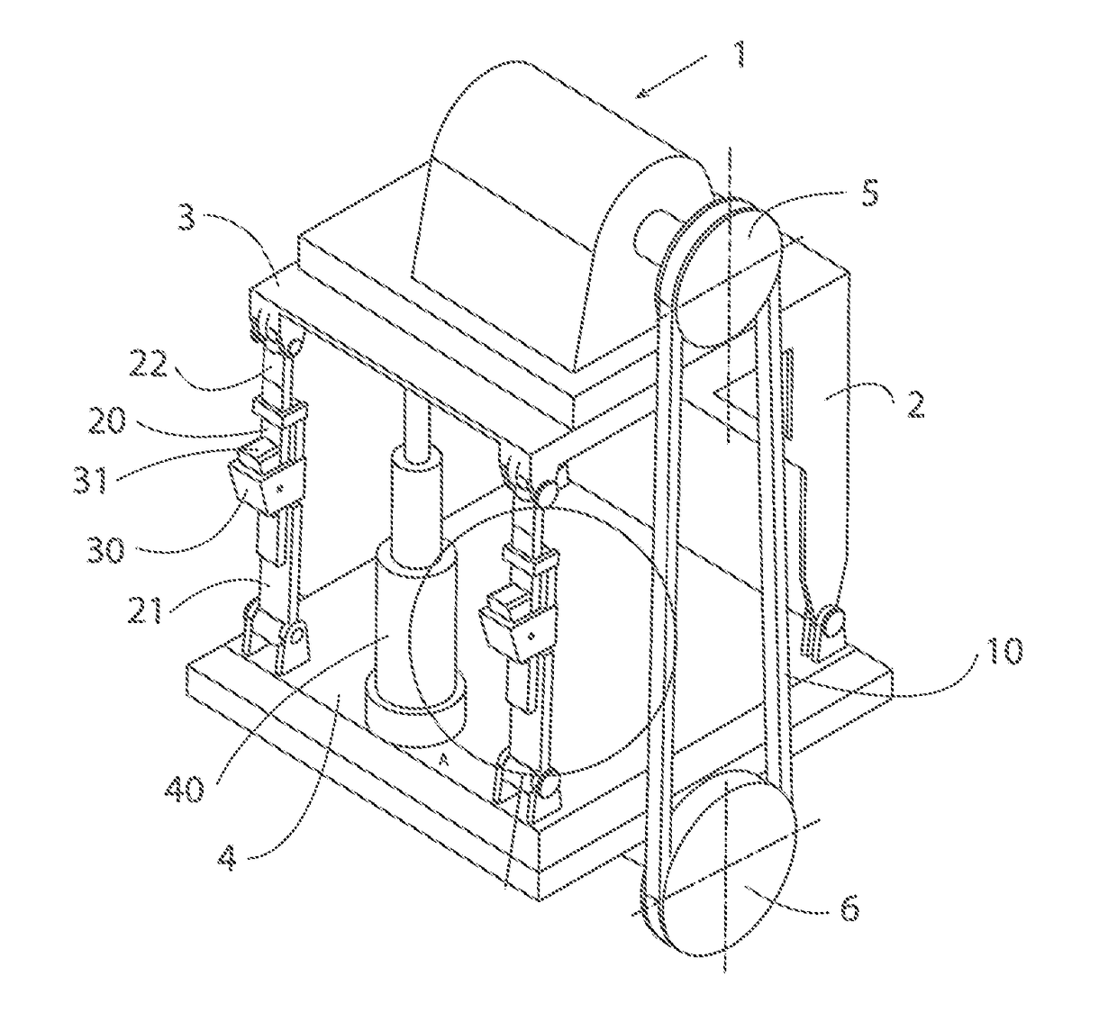
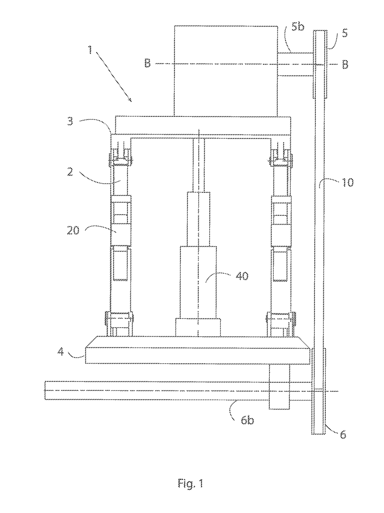
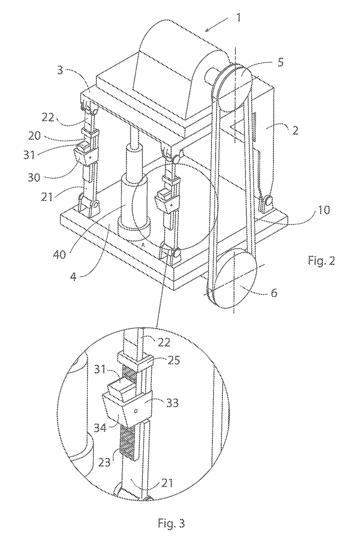
[0020]A machine arrangement 1 belt drive according FIG. 1 comprises a stand 3 having legs 2, said stand with its legs is placed on a base 4. In the illustrated embodiment, a motor / transmission with a driving pulley 5 arranged on a drive shaft 5b placed on the stand and a driven shaft 6b with driven pulley 6 is placed on the base, but it is obvious that the engine / transmission with driving pulley 5 and the driven shaft 6b with the driven pulley 6 can be placed vice versa. The driving pulley 5 and the driven pulley 6 are aligned relative to each other. It is noted that in an embodiment not shown one or more belts 10 may run over more than two pulleys.

[0021]As shown in F...


PUM


Abstract

The invention relates to a device for locking at least one belt (10) at predetermined belt tension, which belt (10) is arranged at a machine arrangement (1) with belt drive. The machine arrangement comprises a stand (3) having legs (2) placed on a base (4). At least one driving pulley (5) and at least one driven pulley (6) are aligned relative to each other. The legs (2) being articulately attached to at least one of the stand (3) or the base (4), and at least two of the legs (2) comprises longitudinally adjustable tension legs (20), which each comprises a first tension leg part (21) having a wedge box (30) arranged to receive a wedge (31) having a grooved surface (32) and a second tension leg part (22) having a grooved surface (23) directed towards said wedge box (30). The first (21) and second (22) tension leg parts are adapted to lock in relation to each other by cooperation between the grooved surface (32) of the wedge (31) and the grooved surface (23) of the second tension leg part (22) when the wedge (31) is adapted to wedge in wedge box (30).

Description

FIELD OF THE INVENTION[0001]The invention relates to a device for locking a belt at predetermined belt tension at a machine arrangement of the kind set out in the preamble of claim 1.BACKGROUND OF THE INVENTION[0002]At machines provided with belt drives with one or more V-belts / belts (in the description below termed belt) between a motor with or without transmission (in the description below termed engine / transmission) and a driven shaft / driven shafts (in the description below termed driven shaft) of a machine a tensioning device for tensioning the belt is used.[0003]More particularly, the belt tension is normally adjusted by a force being applied between the engine / transmission having a driving pulley and a driven pulley of a machine, and at adequate belt tension the distance between the pulleys relative to each other is locked by a threaded locking device, for instance.[0004]Today, the belt tension is adjusted at most belt drives by means of threaded elements, threaded rods and ad...

Claims


Application Information

Patent Timeline
Patent Type & Authority Applications(United States)
IPC IPC(8): F16H7/08F16H7/14
CPCF16H7/0848F16H7/14F16H2007/0851F16H2007/0853F16M7/00
Inventor CEDERSTRAND, TOMMY
Owner F L SMIDTH & CO AS
Why Eureka
Try Eureka