Supercharge Your Innovation With Domain-Expert AI Agents!

Mechanism for lowering a pole

a technology of lowering poles and swivel poles, which is applied in the field of lowering light poles, can solve the problems of affecting the use of swivel poles, and the inability of swivel poles to be suitable for all situations

Active Publication Date: 2018-08-16
KOEKSTONE IP PTY LTD
View PDF6 Cites 1 Cited by
  • Summary
  • Abstract
  • Description
  • Claims
  • Application Information

AI Technical Summary

Benefits of technology

The patent describes a device that limits the rotation of an object. The device has a stop that limits the rotation to a certain point. This stop is either fixed to a base or it is in the middle and rotates with the object. By setting the rotation limit at either 270-300 degrees, the object can rotate around the middle stop and then come back to its original position. This rotation allows for more flexibility and easier manipulation of the object.

Problems solved by technology

Nonetheless, the Swivelpole™ is not suitable for all situations.
In particular, for poles in excess of 4 m in height, and having a heavy luminaire at the remote end, use of the Swivelpole™ becomes problematic due to the high moment generated by the weight of the luminaire.

Method used


Image

  • Mechanism for lowering a pole
  • Mechanism for lowering a pole
  • Mechanism for lowering a pole

Examples


Embodiment Construction

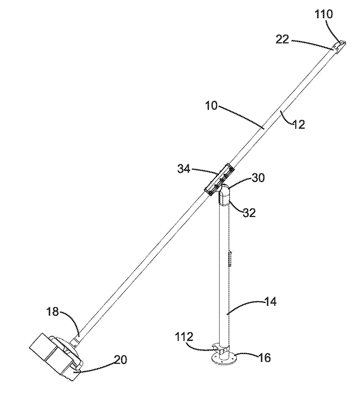
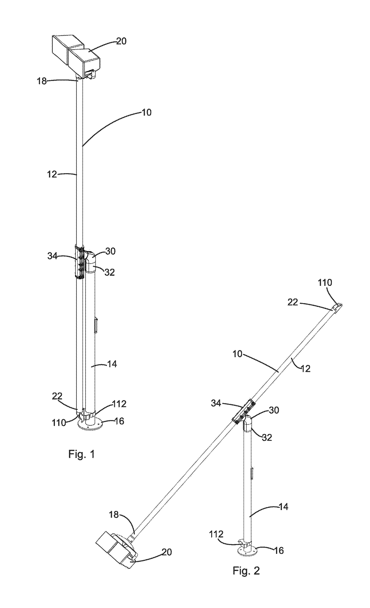
[0040]Referring to the Figures, there can be seen a pole arrangement 10 including an elongate pole member 12 and a pole portion 14. The pole portion 14 is fixed to a base 16, which in use is likely to be on the ground. The pole member 12 has a high end 18 on which a luminaire 20 is mounted, and a low end 22. In the embodiment shown the pole portion 14 has a height of between 2 m and 2.5 m, and the pole member 12 has a length of between 4 m and 5 m. It will appreciated that the pole member 12 may be a single contiguous pole, or may be formed by two separate pole portions.

[0041]The pole member 12 is mounted to the pole portion 14 by means of a pole lowering mechanism 30.

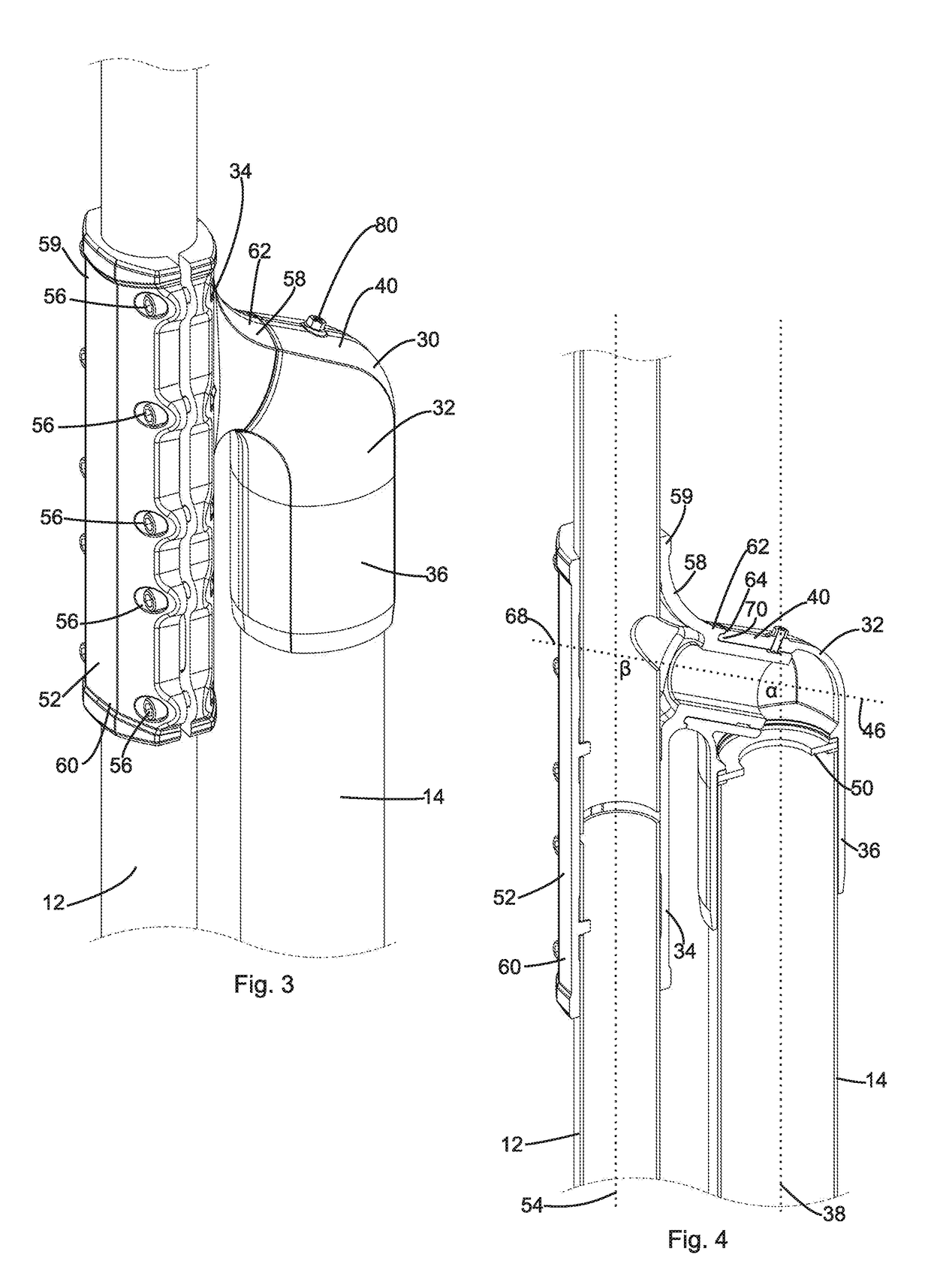
[0042]The pole lowering mechanism 30 has two main pieces: a base 32 and an arm 34.

[0043]The base 32 includes a body portion 36 having a longitudinal axis 38. The body portion 36 is cylindrical, and is arranged to locate over and around the pole portion 14.

[0044]The base 32 also includes a supporting portion 40, located...


PUM


Abstract

A mechanism for lowering a pole, such as a light pole, is disclosed. The mechanism includes a base arranged to rotate about a vertical axis of a pole portion, and an engaging portion arranged to rotate about an operating axis. The operating axis is in the order of 115° relative to the vertical axis. A pole member is fixed to an arm of the engaging portion.

Description

FIELD OF THE INVENTION[0001]The present invention relates to a mechanism for use in lowering light poles and similar structures. The mechanism has been designed for use in light poles in excess of 4 m in height, although it may be used for any light poles having a light located outside of easy reach. It is anticipated that the mechanism may be used in other poles such as flag poles, or in raised elongate structures.BACKGROUND TO THE INVENTION[0002]The Swivelpole™ is described in the International Patent Application published as WO0125687, the contents of which are incorporated herein by reference. This product consists of a light pole which has a swivelling joint along its length. The swivelling joint allows for safer and easier changing and repair of lights than had previously been available.[0003]The Swivelpole™ has proved highly successful, and has become an important safety feature in many industrial, mining, and oil-and-gas installations. Nonetheless, the Swivelpole™ is not sui...

Claims


Application Information

Patent Timeline
Patent Type & Authority Applications(United States)
IPC IPC(8): F21V21/36F21S8/08F21V21/26F16M11/20E04H12/34E04H12/18
CPCF16M13/02E04H12/18F21W2131/103F16M2200/021F16M11/2021E04H12/345F21V21/36F21S8/088F21V21/26F16M2200/044E04H12/187F21S8/085E04H12/34A01K39/00F16L27/08F16M11/06
Inventor PANNEKOEK, ROBERT JOHNPANNEKOEK, PETER
Owner KOEKSTONE IP PTY LTD
Features
  • R&D
  • Intellectual Property
  • Life Sciences
  • Materials
  • Tech Scout
  • Unparalleled Data Quality
  • Higher Quality Content
  • 60% Fewer Hallucinations
Learn More