Ceramic heater

a ceramic heater and heater body technology, applied in the field of ceramic heaters, can solve the problems of restricted degree of freedom in design for the position of temperature measurement, interference of the thermal conductor passage , /b> with an obstacle inside the ceramic plate, etc., and achieve the effect of reducing the surface temperature of the wafer, avoiding the resistance heating element, and being easy to us

Pending Publication Date: 2021-08-05
NGK INSULATORS LTD
View PDF6 Cites 0 Cited by
  • Summary
  • Abstract
  • Description
  • Claims
  • Application Information

AI Technical Summary

Benefits of technology

[0014]In the ceramic heater according to the present invention, the curved portion may be curved in a planar direction of the ceramic plate. With this feature, it is easier to avoid, for example, the hole penetrating through the ceramic plate in the thickness direction of the ceramic plate.
[0015]In the ceramic heater according to the present invention, the curved portion may be curved in the thickness direction of the ceramic plate. With this feature, it is easier to avoid the resistance heating element that is embedded in the ceramic plate substantially parallel to the wafer placement surface. In this case, the terminal end position may be disposed between a plane in the ceramic plate where the resistance heating element is embedded and the wafer placement surface. With this feature, since the terminal end position, namely the position of temperature measurement, is close to the wafer placement surface, a difference between the result of the temperature measurement by a thermocouple and the surface temperature of a wafer is reduced and a more practically useful result can be obtained with the temperature measurement.
[0016]In the ceramic heater according to the present invention, preferably, the curved portion has a curvature radius of 20 mm or more. With this feature, the thermocouple can be relatively smoothly inserted into the thermocouple passage.

Problems solved by technology

However, because the thermocouple passage 426 extends straight in one direction, the thermocouple passage 426 may interfere with an obstacle inside the ceramic plate 420 depending on a position of temperature measurement.
Accordingly, a degree of freedom in design for the position of the temperature measurement is restricted in some cases.

Method used


Image

  • Ceramic heater
  • Ceramic heater
  • Ceramic heater

Examples


Embodiment Construction

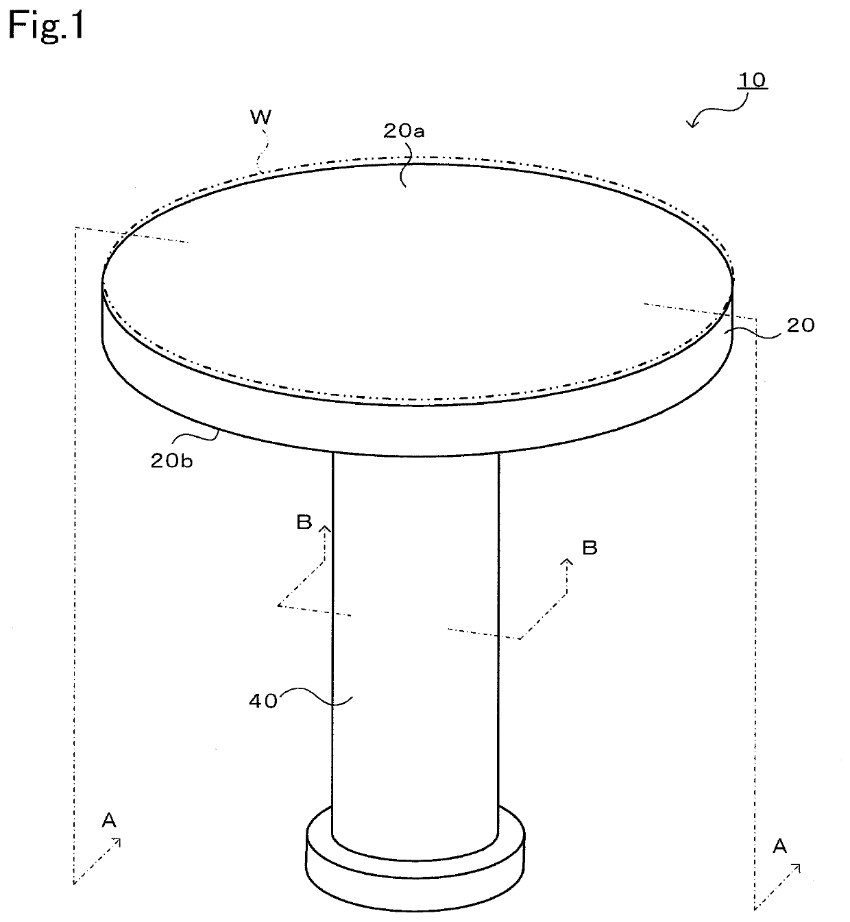
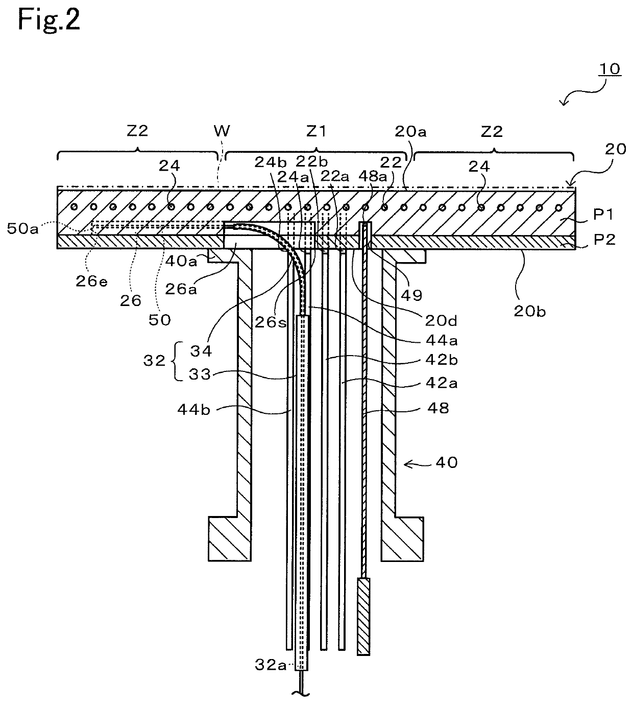
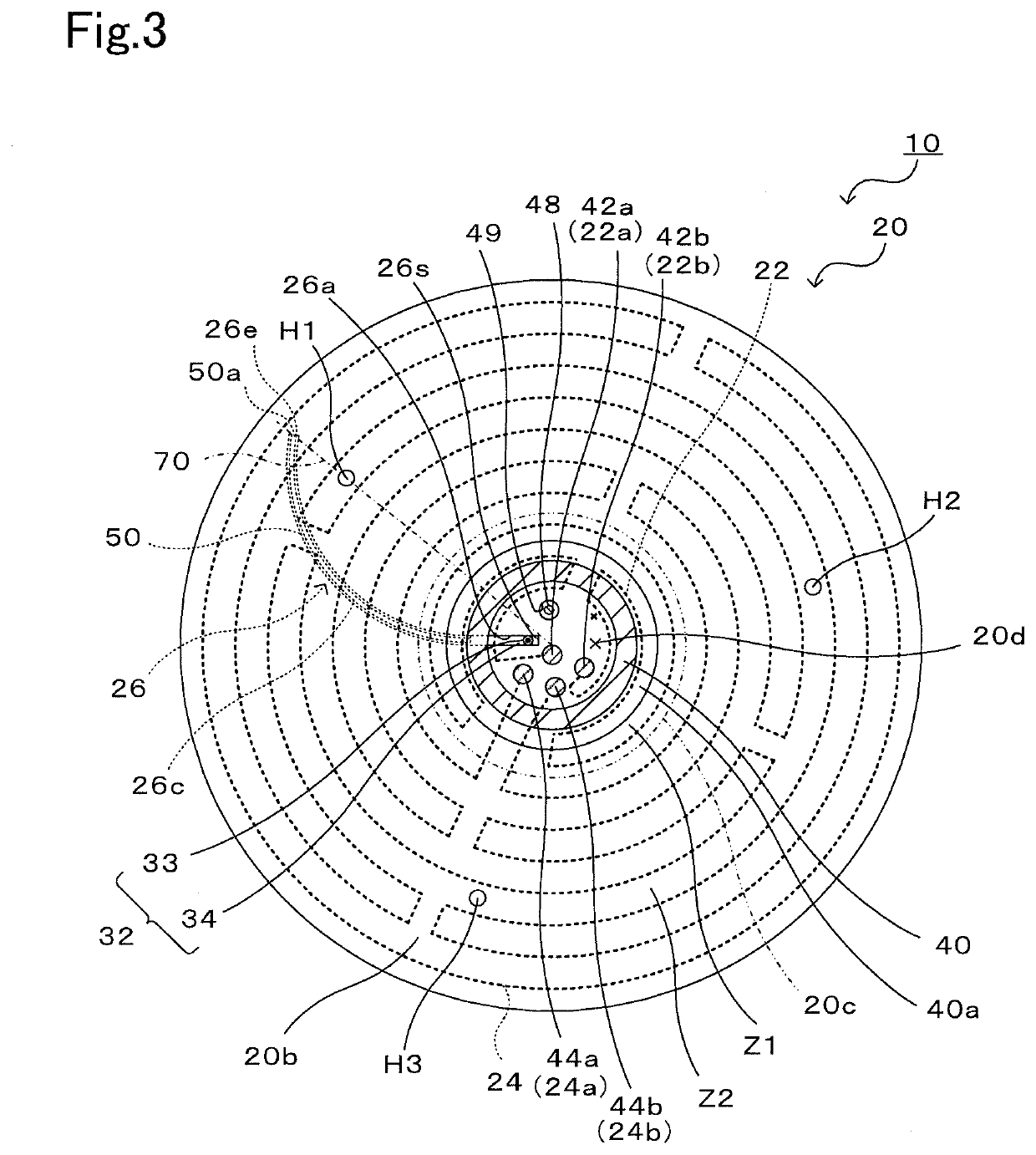
[0028]Preferred embodiments of the present invention will be described below with reference to the drawings. FIG. 1 is a perspective view of a ceramic heater 10, FIG. 2 is a sectional view taken along A-A in FIG. 1, FIG. 3 is a sectional view taken along B-B in FIG. 1, FIG. 4 is a plan view when looking at a thermocouple passage 26 from a rear surface 20b of a ceramic plate 20, FIG. 5 is a front view of a thermocouple guide 32.

[0029]The ceramic heater 10 is used to heat a wafer W on which processing, such as etching or CVD, is to be performed, and is installed within a vacuum chamber (not illustrated). The ceramic heater 10 includes a disk-shaped ceramic plate 20 having a wafer placement surface 20a, and a tubular shaft 40 that is bonded to a surface (rear surface) 20b of the ceramic plate 20 opposite to the wafer placement surface 20a.

[0030]The ceramic plate 20 is a disk-shaped plate made of a ceramic material represented by aluminum nitride or alumina. The diameter of the ceramic...


PUM

PropertyMeasurementUnit
curvature radiusaaaaaaaaaa
diameteraaaaaaaaaa
angleaaaaaaaaaa

Abstract

A ceramic heater includes a ceramic plate having a front surface that serves as a wafer placement surface, resistance heating elements that are embedded in the ceramic plate, a tubular shaft that supports the ceramic plate from a rear surface of the ceramic plate, and a thermocouple passage that extends from a start point in a within-shaft region of the rear surface of the ceramic plate, the within-shaft region being surrounded by the tubular shaft, to a terminal end position in an outer peripheral portion of the ceramic plate. The thermocouple passage includes a curved portion between the start point and the terminal end position.

Description

BACKGROUND OF THE INVENTION1. Field of the Invention[0001]The present invention relates to a ceramic heater.2. Description of the Related Art[0002]As one type of ceramic heater, there has hitherto been known the so-called two-zone heater in which resistance heating elements are embedded independently of each other in an inner peripheral side and an outer peripheral side of a disk-shaped ceramic plate having a wafer placement surface. For example, Patent Literature (PTL) 1 discloses a ceramic heater 410 illustrated in FIG. 10. In the ceramic heater 410, a temperature in an outer peripheral side of a ceramic plate 420 is measured by an outer-peripheral-side thermocouple 450. A thermocouple guide 432 extends straight through the inside of a tubular shaft 440 from a lower side toward an upper side and is then bent in an arch shape to turn 90°. The thermocouple guide 432 is attached to a slit 426a that is formed in a region of a rear surface of the ceramic plate 420, the region being sur...

Claims


Application Information

Patent Timeline
Patent Type & Authority Applications(United States)
IPC IPC(8): H01L21/67H05B1/02H05B3/26
CPCH01L21/67248H05B1/0233H01J37/32724H01L21/67103H05B3/265H05B3/02H05B3/283H05B3/143H01L21/68757H01L21/68785H01L21/68792H05B2203/002
Inventor MATSUSHITA, RYOHEIMOTOYAMA, SHUICHIRO
Owner NGK INSULATORS LTD
Why Eureka
Try Eureka