Redistribution of current demand and reduction of power and dcap

a current demand and power reduction technology, applied in the field of integrated circuit design, can solve the problems of increasing the difficulty of managing power and power related issues in application specific integrated circuits (asics) and standard silicon products (ssps), and the distribution of current demand is far from ideal, so as to reduce or eliminate the need for dcap

Inactive Publication Date: 2009-06-25
AVAGO TECH WIRELESS IP SINGAPORE PTE
View PDF3 Cites 0 Cited by
  • Summary
  • Abstract
  • Description
  • Claims
  • Application Information

AI Technical Summary

Benefits of technology

[0010]The objects, features and advantages of the present invention include providing a method and / or apparatus for redistribution of current demand and reduction of power and DCAP that may (i) provide a delay shift class of cells and cell classification, (ii) provide fine grained path-based circuit switching redistribution, (iii) spread out current spikes, (iv) re-distribute current spikes, (v) be compatible with other power reduction techniques, (vi) reduce or eliminate need for DCAP, (vii) avoid clock tree manipulation, (viii) avoid destabilizing effects of clock tree manipulation, (ix) extend the current technology library, (x) be fully compatible with VT Class and channel length cell swapping techniques for leakage power management, (xi) be used to enhance VT class shifting and channel length swapping, (xii) be highly granular in application, (xiii) cause little or no negative disturbance to a design, (xiv) take little or no increased area over the base library, (xv) eliminate dedication of large areas of a chip to DCAPs, (xvi) eliminate leakage current associated with leaky DCAP cells, (xvii) reduce package costs by allowing for a less expensive package, (xviii) be applicable late in the design flow with little or no impact other than flattening current spikes, (xix) be broadly applicable across nearly all design types, (xx) create very useful results even when the only cells involved are flip-flop cells, (xx) introduce asymmetry with respect to timing arcs and / or (xxi) provide additional incremental benefits when additional cells are involved.

Problems solved by technology

Managing power and power related issues in application specific integrated circuits (ASICs) and standard silicon products (SSPs) is becoming increasingly difficult.
However, because most switching occurs around the clock transitions, most of the time the current demand distribution is far from ideal, as illustrated by the curve 14.
If the spike is not eliminated, problems can occur.
Some examples of problems include: (i) the power grid can ring at some harmonic related to the clock; (ii) the voltage can dip below a storage element retention level; (iii) the timing can fail due to low voltage performance loss.
Higher speed designs that tend to be zero skew in nature can make the problems even worse.
The conventional solutions have significant problems.
The problems become increasingly worse as the frequency of the design increases and when datapath logic is involved.
Decoupling capacitors (DCAPs) are becoming more and more expensive to use.
Both of the above problems, substantial area and leakage increases, represent significant issues that can become progressively worse as circuit geometries shrink and frequencies increase.
Creating a very robust power grid can help somewhat, but is not usually sufficient by itself.
Both decreased routing resources and additional metal layers can represent significant problems.
Moving clocks is possible, but involves progressively increasing complexity, progressive design closure uncertainty and diminishing returns as clock frequencies increase.
There are a number of reasons why moving clocks can be complex.
Because affected timing arcs must still pass timing post optimization, the number of valid targets can be limited or can make the timing results worse.
When the number of valid targets is limited or the timing results worsen, the design can become un-closable.
In addition, as clock frequencies increase, the opportunities to effectively exploit the technique of moving clocks decreases because the relationship between the total clock cycle and the amount of delay associated with the intentional clock tree skew for power degrades.

Method used


Image

  • Redistribution of current demand and reduction of power and dcap
  • Redistribution of current demand and reduction of power and dcap
  • Redistribution of current demand and reduction of power and dcap

Examples


Embodiment Construction

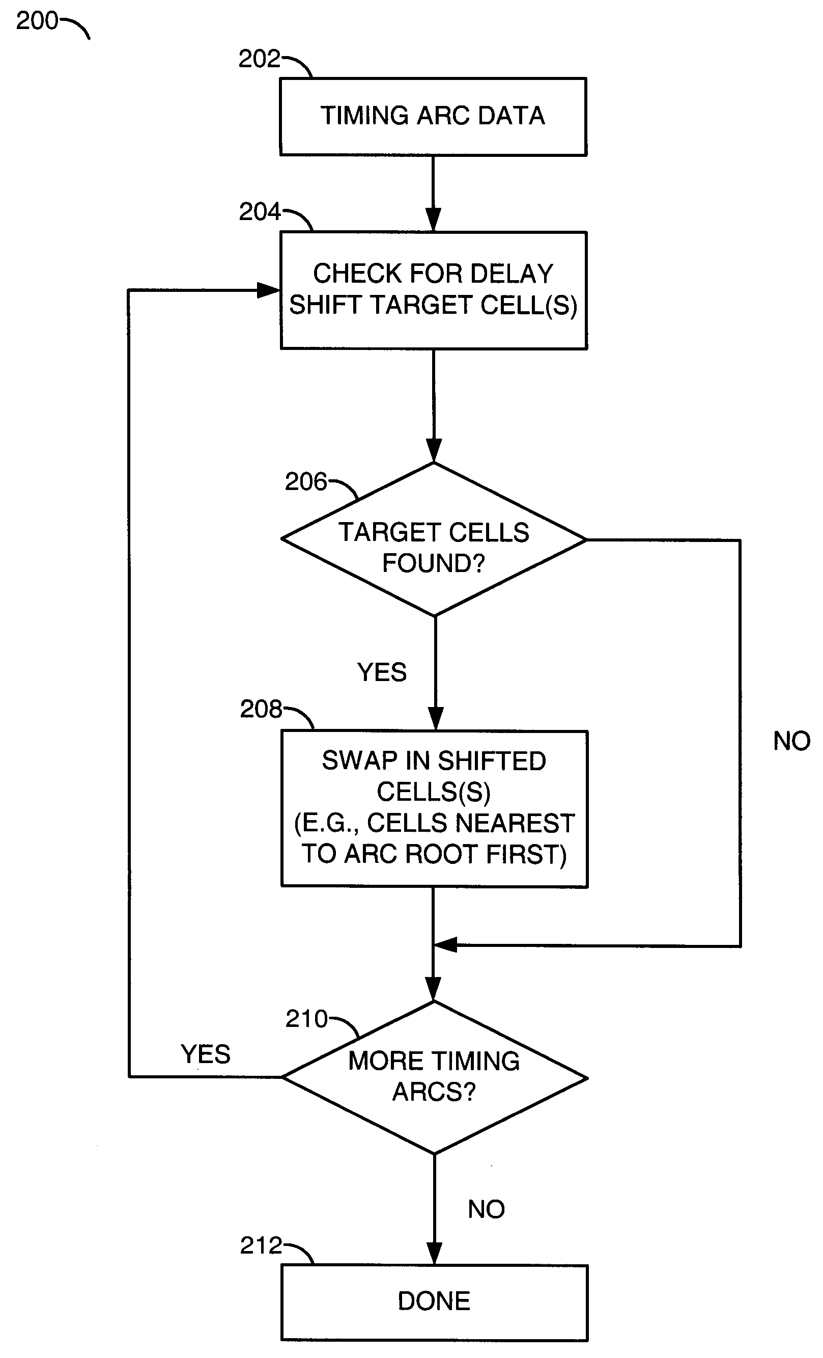
[0017]In one aspect, the present invention generally provides a new type of cell. In one example, the new type of cell may be referred to as a delay shift cell. In some cases new cell designs are implemented. In other cases, a new set of properties may be associated with existing library cells. The properties of the new or modified cells may be used to spread and reduce current spikes. The new or modified cells may be configured to introduce asymmetry with respect to timing arcs of a circuit design. For example, substitution (or swapping) of a base (or standard) cell with a modified (or delay shift) cell may shift a time at which one or more downstream circuits of one or more respective timing arcs may switch. The modified or delay shift cells may retain other key power / performance characteristics such as channel length or voltage threshold (VT) class.

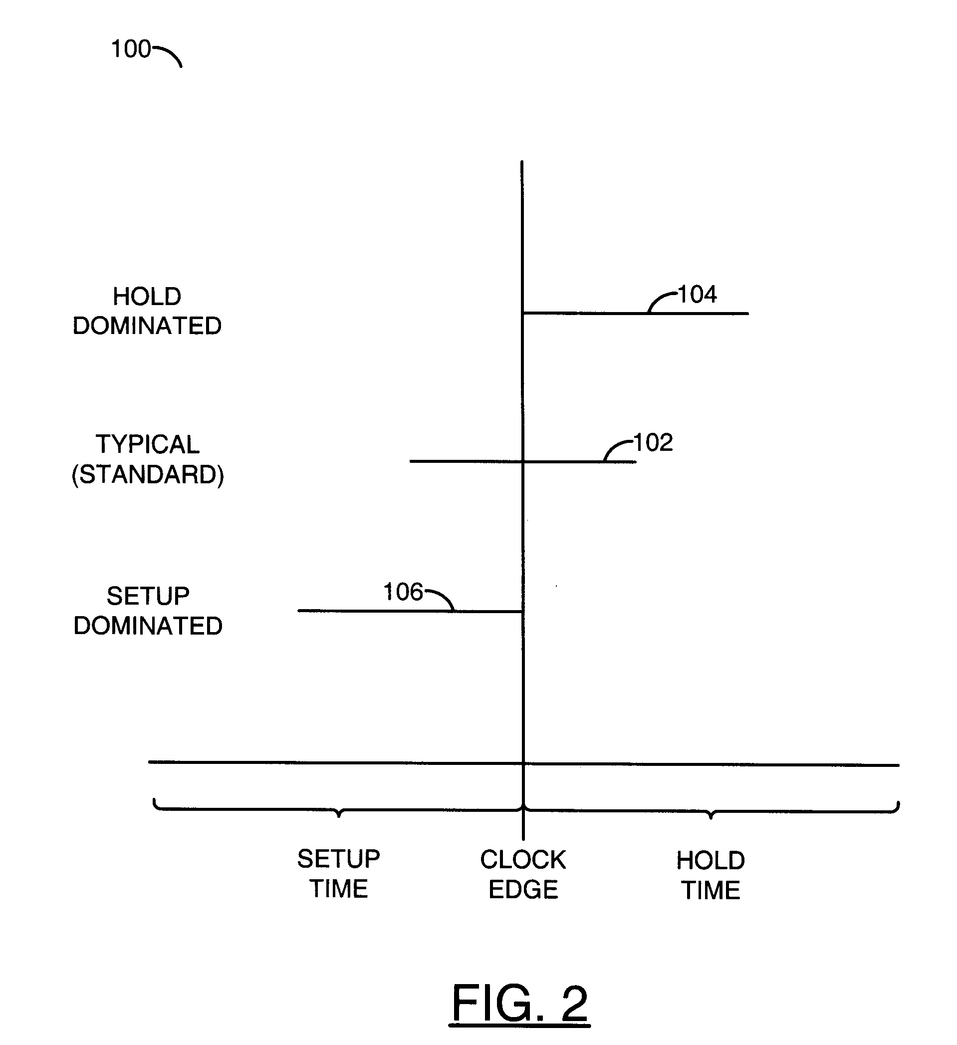
[0018]Referring to FIG. 2, a diagram 100 is shown illustrating adjustment of timing parameters associated with a flip-flop cell imple...


PUM


Abstract

A method to redistribute current demand is presented. The method includes a first step of determining timing arc data for one or more timing arcs of a circuit design. The method includes a second step of checking the timing arc data for delay shift target cells. The method includes a further step of swapping a delay shift target cell with a delay shift cell.

Description

FIELD OF THE INVENTION[0001]The present invention relates to integrated circuit design generally and, more particularly, to a method and / or apparatus to redistribute current demand and reduce power and decoupling capacitance (DCAP).BACKGROUND OF THE INVENTION[0002]Managing power and power related issues in application specific integrated circuits (ASICs) and standard silicon products (SSPs) is becoming increasingly difficult. One area of particular concern is dynamic power and instantaneous current draw in 1 Volt technologies. A current / power spike typically occurs around the switching of a clock or clocks in a design. The design has to provide for the current to switch the circuits. One way the designer can account for the current is with an energy / current density function curve.[0003]Referring to FIG. 1, a diagram 10 is shown illustrating example energy / current density function curves 12 and 14. In an ideal case, all of the current would be evenly distributed during a clock cycle ...

Claims


Application Information

Patent Timeline
Patent Type & Authority Applications(United States)
IPC IPC(8): G06F17/50
CPCG06F2217/84G06F17/5031G06F30/3312G06F2119/12
Inventor BYRN, JONATHAN W.TURNER, MARK F.BROWN, JEFFREY S.
Owner AVAGO TECH WIRELESS IP SINGAPORE PTE
Why Eureka
Try Eureka