Ultrasonic inspection configuration with beam overlap verification

a technology of ultrasonic inspection and beam overlap, applied in the direction of instruments, measurement devices, scientific instruments, etc., can solve problems such as the relative chaos of the way

Inactive Publication Date: 2018-08-16
OLYMPUS SCI SOLUTIONS AMERICAS
View PDF3 Cites 10 Cited by
  • Summary
  • Abstract
  • Description
  • Claims
  • Application Information

AI Technical Summary

Benefits of technology

[0014]During calibration, the beam response is usually acquired without an encoder system, and in a relatively chaotic way. The user typically moves the probe back and forth until the amplitude envelope is smooth—for a sector scan, this means that there is a relatively continuous amplitude response between consecutive angles. Because the data is acquired in such a manner, any method used to extract useful overlap information from the data must be independent of the particular sequence of data acquisition.
[0015]The overlap verification apparatus and method of the present disclosure is based on predetermined relationships between the overlap percentage of adjacent beams and intersection amplitudes of adjacent plots of response amplitude vs probe scan position. These predetermined relationships are used to verify that the overlap percentage of the adjacent beams at a code specified amplitude drop (usually −6 dB) is greater than a predetermined threshold as specified by the relevant code.

Problems solved by technology

During calibration, the beam response is usually acquired without an encoder system, and in a relatively chaotic way.

Method used


Image

  • Ultrasonic inspection configuration with beam overlap verification
  • Ultrasonic inspection configuration with beam overlap verification
  • Ultrasonic inspection configuration with beam overlap verification

Examples


Embodiment Construction

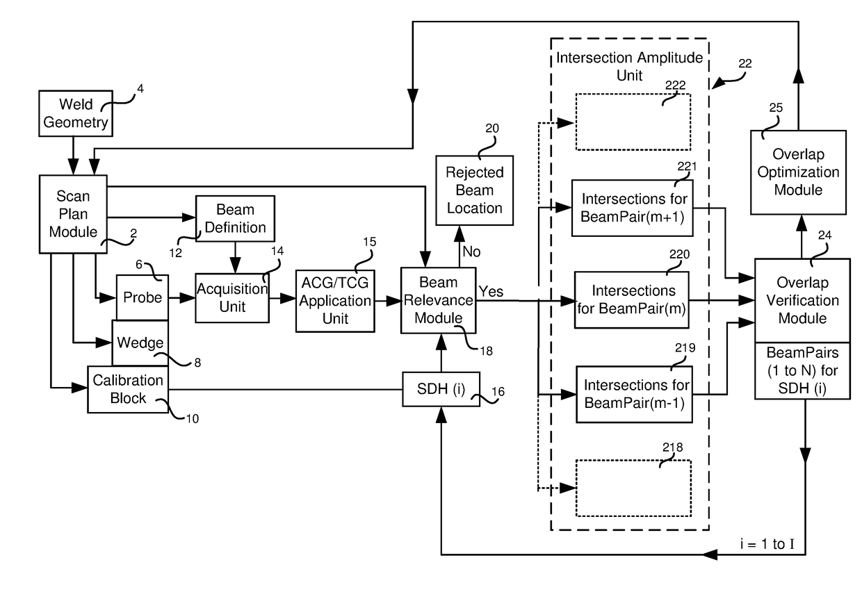
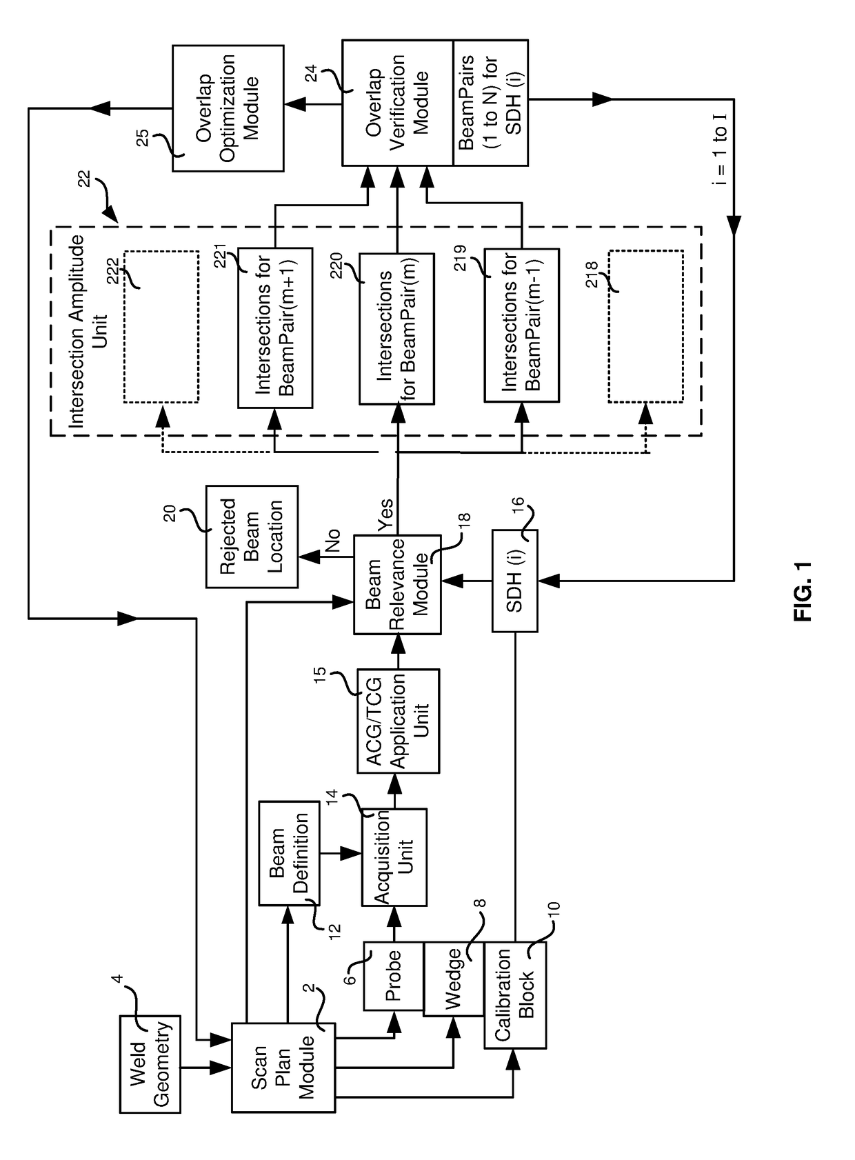
[0022]FIG. 1 shows a schematic flow chart of the overlap verification process during a calibration, which is to be carried out with prior knowledge of the actual geometry for a subsequent measurement on a test object 28. In order to provide suitable ultrasonic beams, a scan plan module 2, having information about a weld geometry 4, is used to generate a beam definition 12, which comprises a definition of N ultrasonic beams having M pairs of adjacent beams. Scan plan module 2 further defines a suitable probe 6, a wedge 8 and a calibration block 10. While probe 6 is generating ultrasonic beams according to scan plan module 2, probe 6 and wedge 8 are manually scanned on the surface of calibration block 10. Acoustic response signals received by probe 6 are directed to a data acquisition unit 14 where the signals are digitized. ACG and TCG calibrations are applied to the digital data by an ACG / TCG application unit 15, and the calibrated data is passed to a beam relevance module 18. Calib...


PUM

PropertyMeasurementUnit
depthaaaaaaaaaa
thresholdaaaaaaaaaa
code overlap thresholdaaaaaaaaaa

Abstract

Disclosed is a beam overlap verification system and method for phased array ultrasonic inspection. A scan plan for the ultrasonic inspection defines a suitable probe, wedge and calibration block having machined defects for the geometry to be inspected, and makes a beam definition which defines a set of ultrasonic beams emitted by the phased array. An intersection amplitude unit records the response amplitudes from each defect at predetermined intersection points of adjacent beam pairs as the probe and wedge are manually scanned across the calibration block. An overlap verification module determines the −6 dB overlap of all adjacent beam pairs which are relevant to the geometry to be inspected, and verifies that the beam overlap conforms to the required coverage according to the ASME or other relevant codes. In this way, coverage is experimentally verified during calibration prior to inspection of a known geometry, such as a weld.

Description

FIELD OF THE INVENTION[0001]The present disclosure generally relates to a method and a system for conducting non-destructive testing / inspection (NDT / NDI) by phased array ultrasonic testing (PAUT), and more particularly to a system and method of creating a scan plan with validation of the overlap of ultrasonic beams of a PAUT configuration.BACKGROUND OF THE INVENTION[0002]Phased array ultrasonic testing (PAUT) is an advanced method of ultrasonic testing that has applications in industrial non-destructive testing (NDT). Common applications are to find flaws in manufactured materials such as welds.[0003]Single-element (non-phased array) probes, known technically as monolithic probes, emit a beam in a fixed direction. To test a large volume of material, a conventional probe must be physically moved or turned to sweep the ultrasonic beam through the area of interest.[0004]In contrast, the beam from a PAUT probe can be moved electronically, without moving the probe, and can be swept throu...

Claims


Application Information

Patent Timeline
Patent Type & Authority Applications(United States)
IPC IPC(8): G01N29/30G01N29/26
CPCG01N29/262G01N29/30G01N29/043G01N29/4427
Inventor LEPAGE, BENOIT
Owner OLYMPUS SCI SOLUTIONS AMERICAS
Why Eureka
Try Eureka