Diffraction gratings formed by metasurfaces having differently oriented nanobeams

Active Publication Date: 2018-08-16
MAGIC LEAP INC
View PDF0 Cites 51 Cited by
  • Summary
  • Abstract
  • Description
  • Claims
  • Application Information

AI Technical Summary

Problems solved by technology

Because the human visual perception system is complex, it is challenging to produce AR technology that facilitates a comfortable, natural-feeling, rich presentation of virtual image elements amongst other virtual or real-world imagery elements.

Method used


Image

  • Diffraction gratings formed by metasurfaces having differently oriented nanobeams
  • Diffraction gratings formed by metasurfaces having differently oriented nanobeams
  • Diffraction gratings formed by metasurfaces having differently oriented nanobeams

Examples


Embodiment Construction

[0195]Optical systems, such as display systems, often utilize optical elements to control the propagation of light. In some applications, due to demand for compact optical systems, conventional optical elements may no longer be suitable.

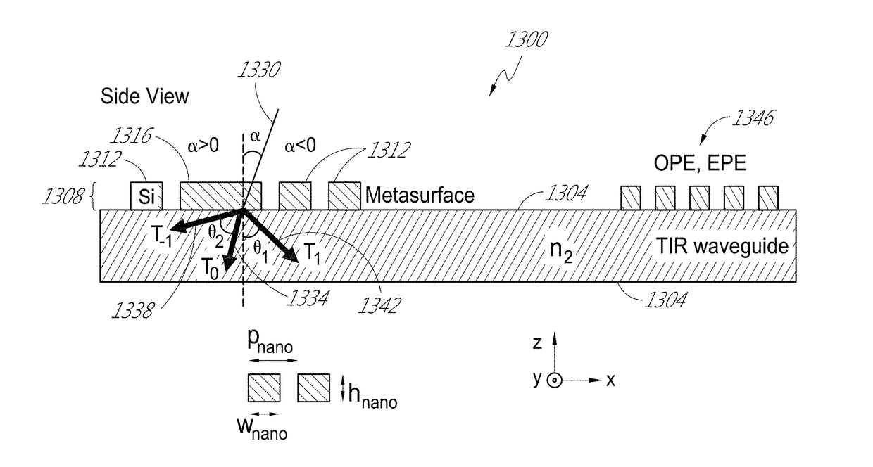
[0196]Metasurfaces, metamaterial surfaces, provide opportunities to realize virtually flat, aberration-free optics on much smaller scales, in comparison with geometrical optics. Without being limited by theory, in some embodiments, metasurfaces include dense arrangements of surface structures that function as resonant optical antennas. The resonant nature of the light-surface structure interaction provides the ability to manipulate optical wave-fronts. In some cases, the metasurfaces may allow the replacement of bulky or difficult to manufacture optical components with thin, relatively planar elements formed by simple patterning processes.

[0197]In some embodiments, metasurfaces for forming diffractive gratings are disclosed. The metasurfaces may take...


PUM


Abstract

Metasurfaces provide compact optical elements in head-mounted display systems to, e.g., incouple light into or outcouple light out of a waveguide. The metasurfaces may be formed by a plurality of repeating unit cells, each unit cell comprising two sets or more of nanobeams elongated in crossing directions: one or more first nanobeams elongated in a first direction and a plurality of second nanobeams elongated in a second direction. As seen in a top-down view, the first direction may be along a y-axis, and the second direction may be along an x-axis. The unit cells may have a periodicity in the range of 10 nm to 1 μm, including 10 nm to 500 nm or 300 nm to 500 nm. Advantageously, the metasurfaces provide diffraction of light with high diffraction angles and high diffraction efficiencies over a broad range of incident angles and for incident light with circular polarization.

Description

PRIORITY CLAIM[0001]This application claims the benefit of priority under 35 U.S.C. § 119(e) of U.S. Provisional Application No. 62 / 451,608 filed on Jan. 27, 2017 and U.S. Provisional Application No. 62 / 451,615 filed on Jan. 27, 2017. The entire disclosure of each of these priority documents is incorporated herein by reference.INCORPORATION BY REFERENCE[0002]This application incorporates by reference the entirety of each of the following patent applications: U.S. application Ser. No. 14 / 331,218 (Magic Leap docket no. 20020.00); U.S. application Ser. No. 14 / 641,376 (Magic Leap docket no. 20014.00); U.S. Provisional Application No. 62 / 012,273 (Magic Leap docket no. 30019.00); U.S. Provisional Application No. 62 / 005,807 (Magic Leap docket no. 30016.00); U.S. Provisional Application No. 62 / 333,067 (Attorney Docket no. MLEAP.066PR); and U.S. patent application Ser. No. 15 / 342,033 (Attorney Docket no. MLEAP.027A).BACKGROUNDField[0003]The present disclosure relates to display systems and, ...

Claims


Application Information

Patent Timeline
Patent Type & Authority Applications(United States)
IPC IPC(8): G02B5/18G02B27/01F21V8/00
CPCG02B5/1871G02B5/1842G02B27/0172G02B5/1809G02B6/0016G02B2207/101G02B6/00G02B6/0011G03H1/0244B82Y20/00G03H2222/31G03H2223/16G02B1/02
Inventor LIN, DIANMINKLUG, MICHAEL ANTHONYST. HILAIRE, PIERREMELLI, MAUROPEROZ, CHRISTOPHEPOLIAKOV, EVGENI
Owner MAGIC LEAP INC
Why Eureka
Try Eureka