Chassis structure

a chassis and structure technology, applied in the field of chassis structure, can solve the problems of consuming more labor and time, producing much waste of material, etc., and achieve the effect of simplifying the manufacturing process and saving manufacturing costs

Active Publication Date: 2018-08-16
LITE ON ELECTRONICS (GUANGZHOU) LTD +1
View PDF21 Cites 2 Cited by
  • Summary
  • Abstract
  • Description
  • Claims
  • Application Information

AI Technical Summary

Benefits of technology

[0005]The embodiments of the invention provide a chassis structur...

Problems solved by technology

In the foregoing design, the box body is manufactured in two phases, wh...

Method used


Image

  • Chassis structure
  • Chassis structure
  • Chassis structure

Examples


Embodiment Construction

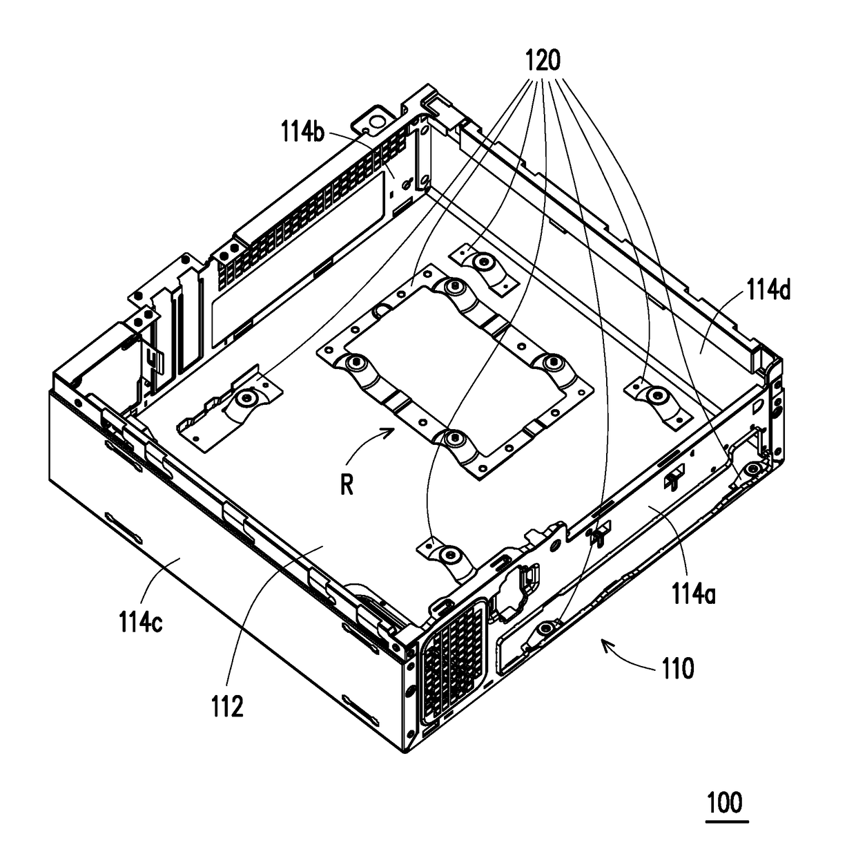
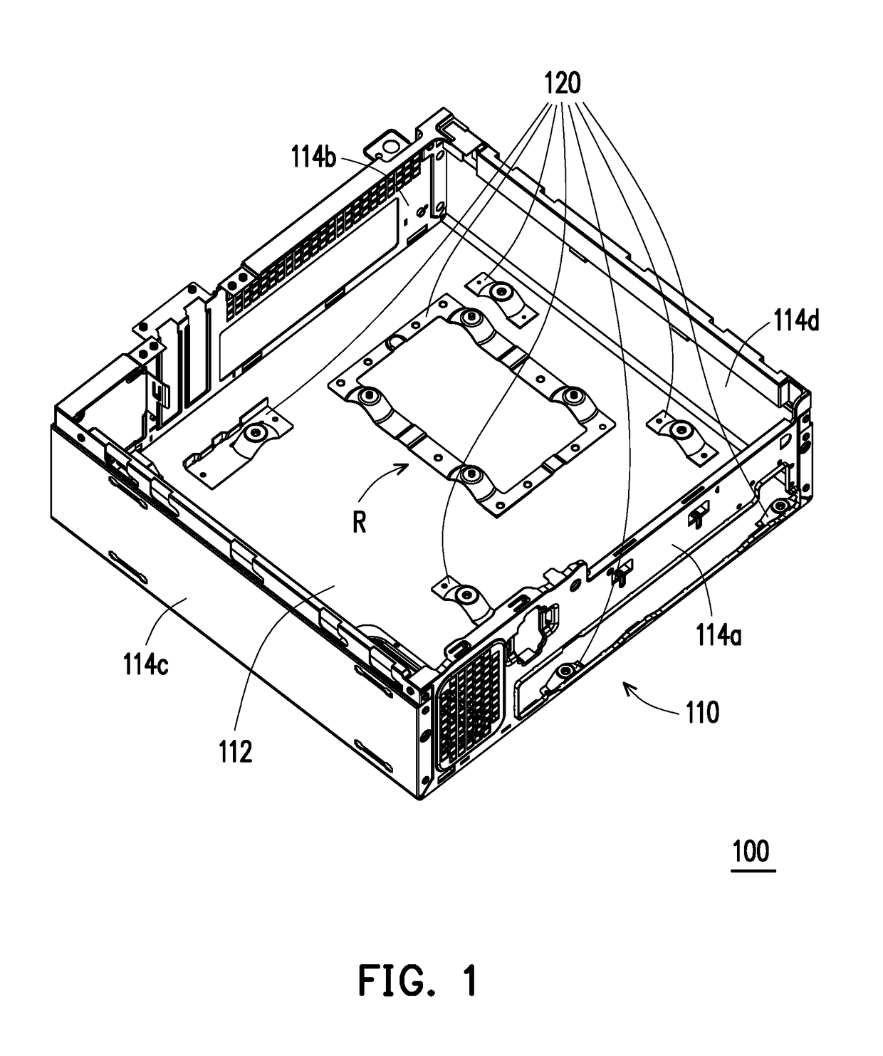
[0041]FIG. 1 is a perspective view illustrating a chassis structure according to an embodiment of the invention. FIG. 2 is a perspective view illustrating the chassis structure of FIG. 1 from another perspective. FIG. 3 is a top view illustrating the chassis structure of FIG. 1. Referring to FIG. 1 to FIG. 3, a chassis structure 100 of the present embodiment includes a box body 110 and a plurality of assembling components 120. The box body 110 includes a main plate 112 and a plurality of side plates 114a to 114d, wherein the side plates 114a to 114d surround a periphery of the main plate 112 and define an accommodating space. The assembling components 120 are bonded to the main plate 112 and are located in the accommodating space.

[0042]In the embodiments of the invention, the box body 110 is formed of one single metal component to provide an integral box body 110 (i.e., the main plate 112 and the side plates 114a to 114d form an integral structure). Different from the conventional d...


PUM


Abstract

A chassis structure including a box body and a plurality of assembling components is provided. The box body includes a main plate and a plurality of side plates, wherein the side plates surround a periphery of the main plate and define an accommodating space. The assembling components are bonded to the main plate and are located in the accommodating space.

Description

CROSS-REFERENCE TO RELATED APPLICATION[0001]This application claims the priority benefit of U.S. provisional application Ser. No. 62 / 459,608, filed on Feb. 16, 2017 and China application serial no. 201810006901.X, filed on Jan. 4, 2018. The entirety of each of the above-mentioned patent applications is hereby incorporated by reference herein and made a part of this specification.BACKGROUND OF THE INVENTIONField of the Invention[0002]The disclosure relates to a chassis structure, and in particular, to a chassis structure including a plurality of assembling components.Description of Related Art[0003]As technology advances, personal computers have been widely applied in work and life. Common personal computers currently include desktop computers and notebook computers.[0004]In terms of desktop computers, a host chassis may be disassembled into a box body and a cover plate. Generally, the box body is formed by stacking two metal components, i.e., a first metal component and a second met...

Claims


Application Information

Patent Timeline
IPC IPC(8): G06F1/18
CPCG06F1/181G06F1/183G06F1/184G06F1/188
Inventor CHIU, LIANG-CHENG
Owner LITE ON ELECTRONICS (GUANGZHOU) LTD
Why Eureka
Try Eureka