Display Arrangement for Watch Case

a technology for display cases and watches, applied in applications, instruments, horology, etc., can solve the problems of reducing the time available, drawing a significant amount of power, and difficult for users to discern whether leds are illuminated

Inactive Publication Date: 2018-08-23
TOMTOM INT BV
View PDF0 Cites 42 Cited by
  • Summary
  • Abstract
  • Description
  • Claims
  • Application Information

AI Technical Summary

Benefits of technology

[0039]The watch case may comprise one or more electrical connectors for electrically connecting to a dock or cable for charging the battery and / or for transferring data to or from the processor. It is contemplated that any known electrical connector may be employed. In preferred embodiments, however, the one or more electrical connectors comprise electrical contacts, which may be flat and arranged substantially in line with, or recessed in, the lower surface of the case (e.g. for contacting with corresponding pogo pins in a docking system). The electrical contacts may be located in any portion of the lower surface of the case as desired, although in preferred embodiments the electrical contacts are located in the lower surface under the input device, e.g. distal from the display housing. This allows the user to see the display when the module is positioned in a docking system.

Problems solved by technology

However, the LEDs used for backlighting can draw a significant amount of power and seriously reduce the time available until the watch battery needs to be recharged.
This LED arrangement, however, typically requires a transparent cover over the LEDs and this means that the underlying LEDs are visible even when not illuminated, which can cause confusion.
Especially when viewing the watch display in daylight conditions, it can be difficult for a user to discern whether such LEDs are illuminated or not.

Method used


Image

  • Display Arrangement for Watch Case
  • Display Arrangement for Watch Case
  • Display Arrangement for Watch Case

Examples


Embodiment Construction

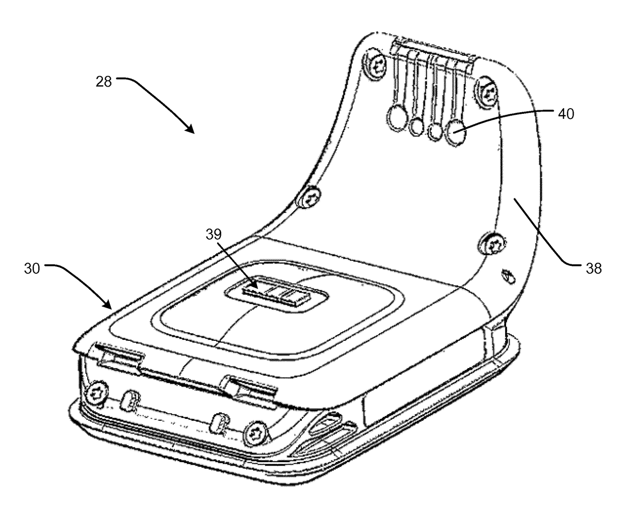
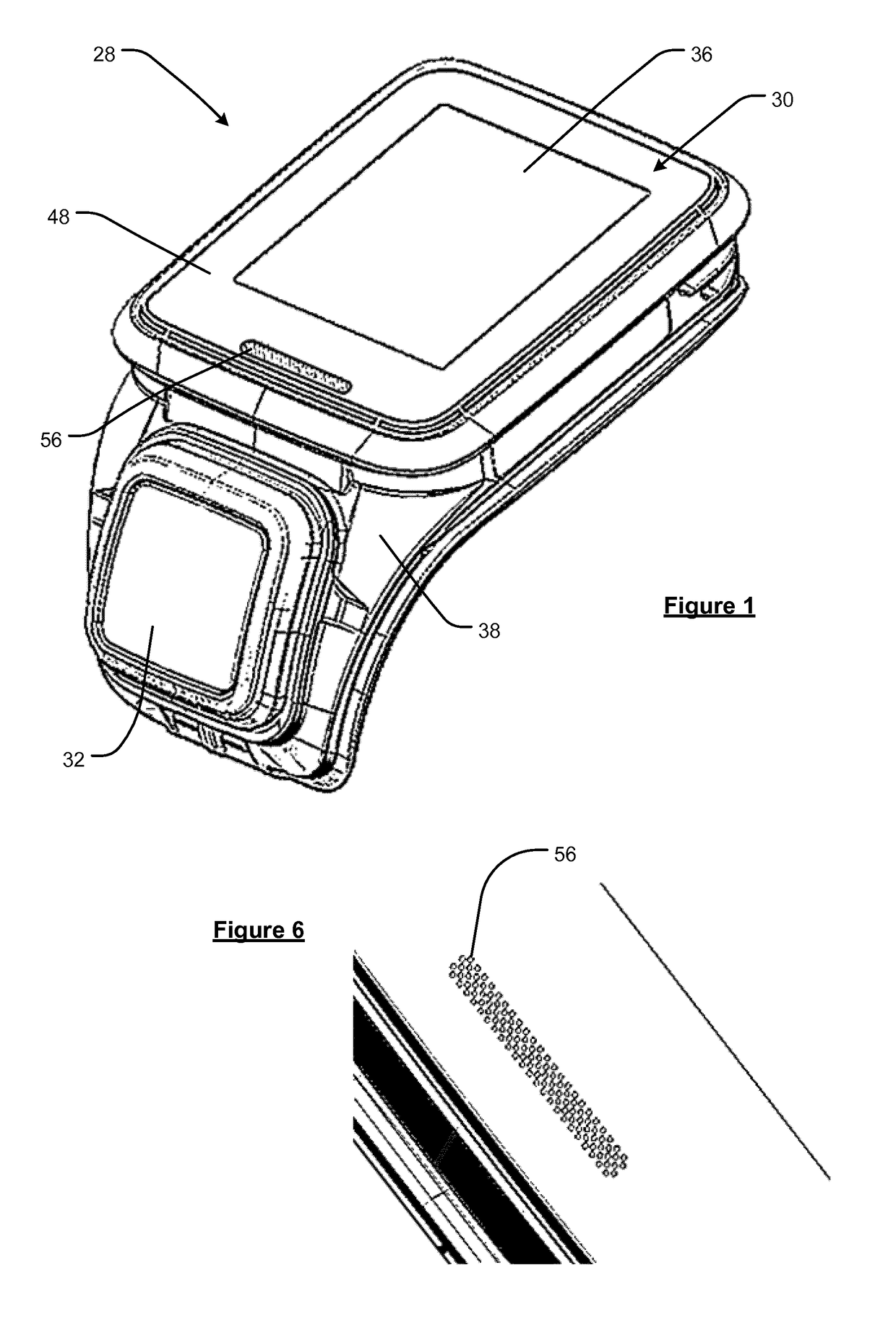
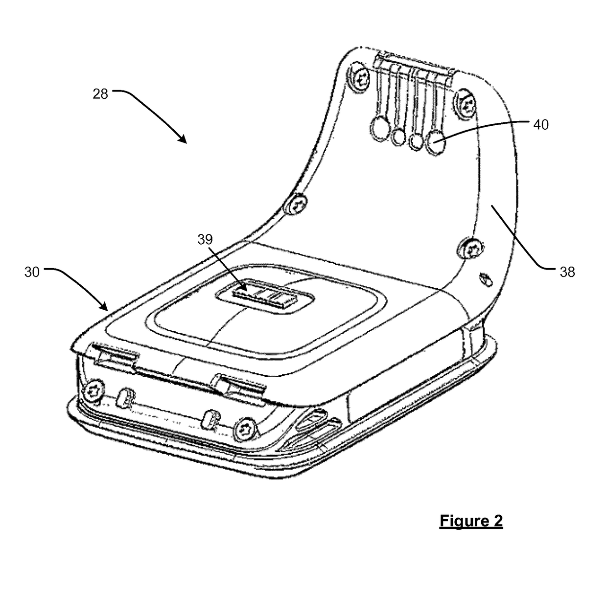
[0052]Preferred embodiments of the present invention will now be described with particular reference to a fitness or sports watch having access to Global Positioning System (GPS) data. Fitness or sports watches of the type described are often worn by athletes to help them during their runs or workouts, e.g. by monitoring the speed and distance of the user and providing this information to the user. It will be appreciated, however, that the device could be arranged to be carried by a user or connected or “docked” in a known manner to a vehicle such as a bicycle, kayak, or the like.

[0053]In general, GPS is a satellite-radio based navigation system capable of determining continuous position, velocity, time, and in some instances direction information for an unlimited number of users. Formerly known as NAVSTAR, the GPS incorporates a plurality of satellites which orbit the earth in extremely precise orbits. Based on these precise orbits, GPS satellites can relay their location to any nu...


PUM


Abstract

A display arrangement for a watch case comprising a display module and a substantially transparent cover extending over the display module, wherein the cover comprises a layer forming a substantially opaque area outside the display module. The display arrangement further comprises one or more light emitting devices arranged below the opaque area, wherein the layer comprises a plurality of discontinuities that allows light to be transmitted through the opaque area from the one or more light emitting devices.

Description

FIELD OF THE INVENTION[0001]This invention relates to displays for fitness watches and other wearable sensors such as heart rate monitors. The display may be provided as part of a watch case that is mounted, permanently or removably, to a strap so as to be worn on a user's wrist. Illustrative embodiments of the invention relate to fitness watches for monitoring athletic performance, e.g. that can be worn during an exercise activity (running, cycling, swimming, hiking, skiing, weightlifting, etc.), which can track and display information relating to a user's activity levels, such as the heart rate of the user at particular moments during a workout.BACKGROUND OF THE INVENTION[0002]Conventional fitness watches typically comprise a liquid crystal display (LCD) module in the watch case. The LCD module may be backlit by one or more light emitting diodes (LEDs). Some fitness watches, e.g. the TomTom® Runner watch, can be used with or without wireless connection to a separate heart rate mon...

Claims


Application Information

Patent Timeline
Patent Type & Authority Applications(United States)
IPC IPC(8): A61B5/024A61B5/00A61B5/11G04G21/02G04G17/04G04G9/00
CPCA61B5/7445G04G21/025G04G17/045G04G9/0041G04G21/04A61B5/02427A61B5/681A61B5/1112A61B5/0022A61B5/1118A61B5/02438A61B2562/0219G04G9/0035
Inventor BAYLEY, STEPHENMORGAN, DAVID
Owner TOMTOM INT BV
Why Eureka
Try Eureka