
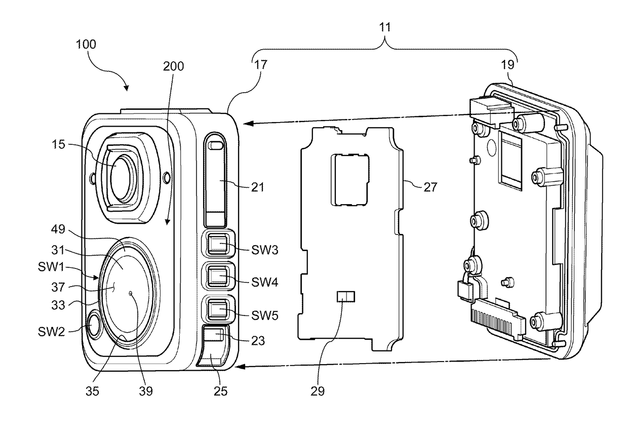
Pressing switch mechanism and wearable camera

a technology of a switch and a wearable camera, which is applied in the field of pressing switch mechanism and wearable camera, can solve the problems of difficult to verify the legitimacy of a response during regular patrolling of a police officer or a response at the time of an emergency dispatch request, the police officer hardly knows whether or not the switch operation has been appropriately performed by the police officer, etc., and achieves the effect of simple structure and high efficiency

Active Publication Date: 2018-08-23
PANASONIC I PRO SENSING SOLUTIONS CO LTD
View PDF17 Cites 5 Cited by
  • Summary
  • Abstract
  • Description
  • Claims
  • Application Information

AI Technical Summary

Benefits of technology

The patent aims to provide a pressing switch mechanism and a wearable camera that can efficiently generate a click feeling and operation sound with a simple structure. Additionally, it aims to reduce the difficulty for the user to understand whether or not a switch operation was performed. The technical effects of the invention include high efficiency and a simple structure, as well as improved user experience and reduced difficulty in understanding switch operation.

Problems solved by technology

In recent years, for example, in the United States, a difficulty of verifying the legitimacy of a response during regular patrolling of a police officer or a response at the time of an emergency dispatch request (for example, firing of a handgun) has been a problem.
However, in this case, for example, under urgent and tense situations, in the configuration disclosed in Japanese Patent Unexamined Publication No. 2016-122115, the police officer hardly knows whether or not the switch operation has appropriately been performed by the police officer (in other words, whether or not the recording button has been properly pressed by the police officer).

Method used


Image

  • Pressing switch mechanism and wearable camera
  • Pressing switch mechanism and wearable camera
  • Pressing switch mechanism and wearable camera

Examples


Embodiment Construction

[0015]Hereinafter, exemplary embodiments in which a pressing switch mechanism and a wearable camera according to the disclosure are disclosed (hereinafter, referred to as the “exemplary embodiment”) will be described in detail with reference to the drawings as appropriate. However, more detailed description than necessary may be omitted. There are cases where detailed descriptions of well-known matters and redundant descriptions on substantially the same configuration may be omitted. This is to avoid the unnecessary redundancy of the following description and to facilitate understanding by those skilled in the art. The accompanying drawings and the following description are provided to enable those skilled in the art to fully know the disclosure, and are not intended to limit the matters described in the claims.

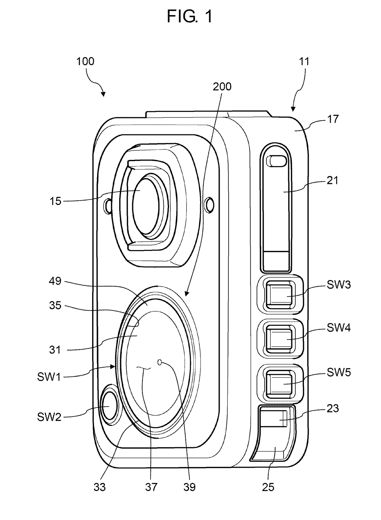
[0016]FIG. 1 is a perspective view of the wearable camera of the exemplary embodiment.

[0017]As an example of a user of wearable camera 100 according to the exemplary embodime...


PUM


Abstract

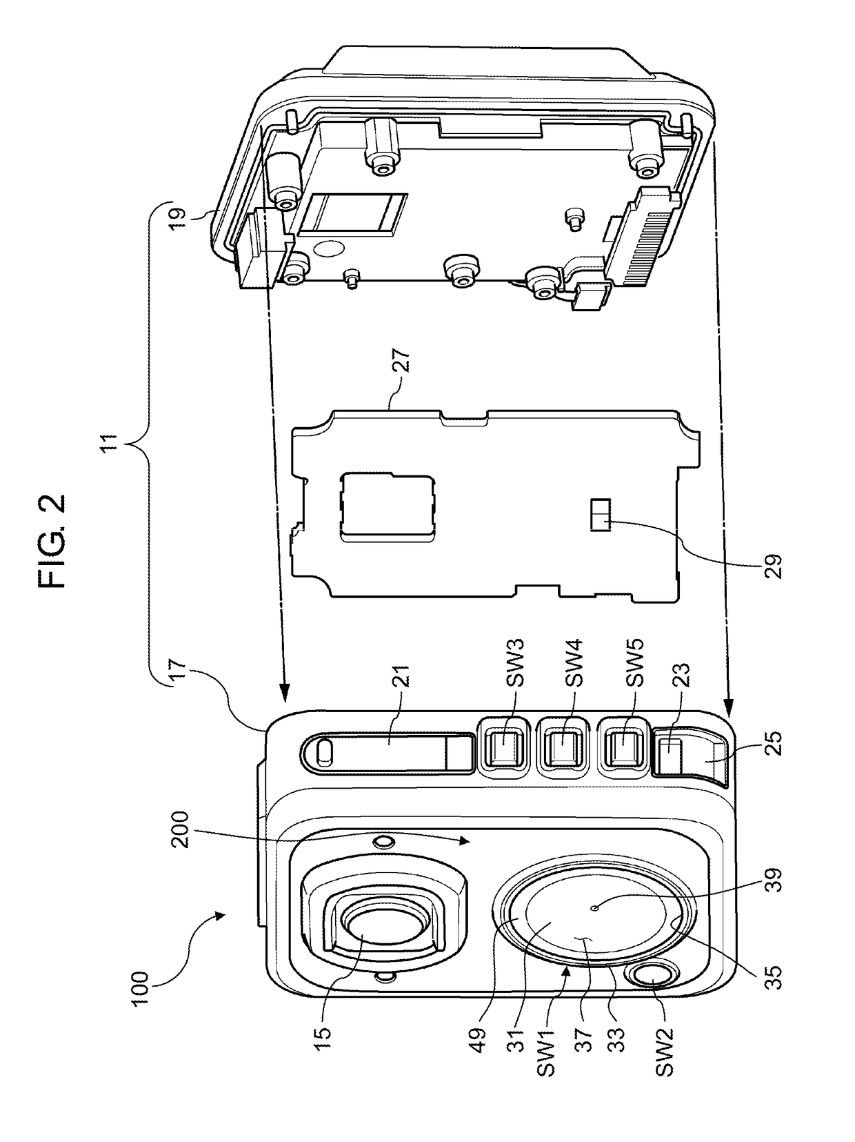
A pressing switch mechanism includes a housing, a board that is accommodated in the housing, a switch portion that is fixed to the board and generates a click feeling according to pressing a pressed portion in a direction approaching the board, and an operation plate which includes a bowl-shaped recessed surface that is recessed from a surface of the housing, of which an outer peripheral edge is supported by the housing, which is displaceably bent in the direction approaching the board, and in which a bottom wall portion of the recessed surface protruding inward the housing is in contact with the pressed portion.

Description

BACKGROUND1. Technical Field[0001]The present disclosure relates to a pressing switch mechanism in which a switch is pressed by a user and a wearable camera including the pressing switch mechanism.2. Description of the Related Art[0002]In recent years, for example, in the United States, a difficulty of verifying the legitimacy of a response during regular patrolling of a police officer or a response at the time of an emergency dispatch request (for example, firing of a handgun) has been a problem. Therefore, during patrolling or emergency dispatch request, in order to accurately image a situation of a site as a destination of the police officer, and then use it for the verification of legitimacy of the response of the police officer, an operation of attaching a wearable camera on the police officer during patrolling or at the time of a support dispatch is promoted. A recording button for recording data of an image captured by the wearable camera is usually provided in the wearable c...

Claims


Application Information

Patent Timeline
IPC IPC(8): H01H13/48H04N5/225H01H13/04
CPCH01H13/48H04N5/2252H01H2215/004H01H2231/046H01H13/04H01H13/84H01H2215/006H01H2215/03H01H2217/004H01H2221/05H04N23/51
Inventor OOMORI, YASUHITOTOBIMATSU, TATSUYATAKADA, NOBORUTAKAHASHI, EIJISATO, IZUMI
Owner PANASONIC I PRO SENSING SOLUTIONS CO LTD
Learn More