

Three-dimensional printing of three-dimensional objects
a three-dimensional object and printing technology, applied in auxillary welding devices, program control, instruments, etc., can solve the problem of diminished number of defects in 3d objects, and achieve the effect of reducing porosity and high aspect ratio
- Summary
- Abstract
- Description
- Claims
- Application Information
AI Technical Summary
Benefits of technology
Problems solved by technology
Method used
Image

Examples
example 1
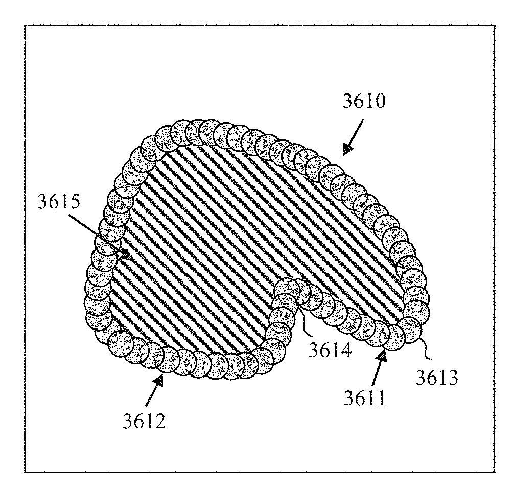
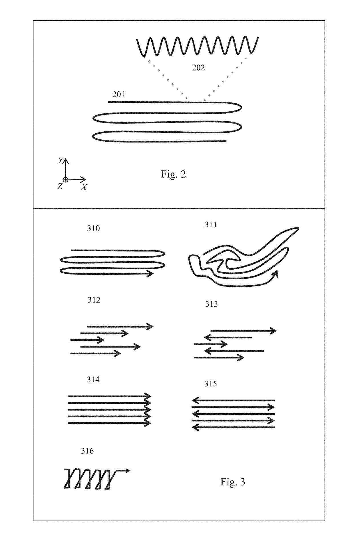
[0387]In a 28 cm by 28 cm by 30 cm container at ambient temperature and pressure. Inconel 718 powder of average particle size 35 μm is deposited in a container to form a powder bed. The container is disposed in an enclosure to separate the powder bed from the ambient environment. The enclosure is purged with Argon gas for 30 minutes. A 500 W fiber laser beam was used to melt a portion of the powder bed and generate two substantially identical 3D objects, each comprising an extended ledge that was anchored on one of its side to the base using auxiliary supports. The ledge in each of the two 3D objects had an angle (e.g., of about 25°) with respect to the base, in which the laser beam path followed a path scheme resembling the one shown in the example of FIG. 3, 314. The 3D objects were fabricated by successive deposition of layers of powder material having an average thickness of about 50 μm and melting portions of each of the successively deposited layers using the laser beam. The a...
example 2
[0388]In a 28 cm by 28 cm by 30 cm container at ambient temperature and pressure, Inconel 718 powder of average particle size 35 μm is deposited in a container to form a powder bed. The container is disposed in an enclosure to separate the powder bed from the ambient environment. The enclosure is purged with Argon gas for 30 minutes. A 500 W fiber laser beam was used to melt a portion of the powder bed and form a skin (contour) of a 3D object. The contour was formed by transforming layers of powder material having an average thickness of about 50 μm using a tiling methodology (type-2 energy beam), as described herein. The internal portions of the 3D object layers were formed using a methodology of forming the rigid-portion (e.g., using hatches) as described herein. Images of 3D objects in which a skin (contour) is formed using contour methodology are shown in FIGS. 38A and 38B. The surface roughness of the 3D objects depicted in FIGS. 38A and 38B was measured using the Keyence VR-32...
example 3
[0389]In a 300 mm diameter and 400 mm high container at ambient temperature. Inconel 718 powder of average particle size 35 μm is deposited in a container to form a powder bed. The container is disposed in an enclosure to separate the powder bed from the ambient environment. The enclosure is purged with Argon gas. A 1000 W fiber laser beam was used to melt a portion of the powder bed and form an overhang of a 3D object at an angle with respect to the platform base. The overhang was formed by transforming layers of powder material having an average thickness of about 50 μm using a MTO process as described herein. A first transformation operation was performed used a hatching methodology (type-1 energy beam). A SEM image of the 3D object after the first transformation operation is shown in FIG. 54A using the Nova™ NanoSEM 630. A second transformation operation was performed using a HARMP methodology to re-transform (e.g., remelt) at least a portion of the previously transformed materi...
PUM
| Property | Measurement | Unit |
|---|---|---|
| Thickness | aaaaa | aaaaa |
| Thickness | aaaaa | aaaaa |
| Angle | aaaaa | aaaaa |
Abstract
Description
Claims
Application Information