
Light-emitting device

a technology of light-emitting devices and led elements, which is applied in the direction of semiconductor devices, basic electric elements, electrical appliances, etc., can solve the problems of complicated control of electric currents for adjusting hues, difficult to mix light from led elements, etc., and achieve high color rendering performance and color mixing properties. the effect of improving efficiency and light-emitting efficiency

Active Publication Date: 2018-09-06
CITIZEN ELECTRONICS CO LTD +1
View PDF2 Cites 5 Cited by
  • Summary
  • Abstract
  • Description
  • Claims
  • Application Information

AI Technical Summary

Benefits of technology

The present invention provides a light-emitting device that improves color mixing and light emission efficiency. This device uses four kinds of LED elements emitting red, green, blue, and white light to create high-quality white light with vivid color rendering performance. The device also includes a resin frame with an inner white resin layer for reflecting light and an outer black resin layer for preventing outward light transmission. Additionally, the device includes a light-shielding component made up of an inner white sheet for reflecting light and an outer black sheet for preventing outward light transmission. Overall, this device enhances color mixing and light emission efficiency while ensuring the desired white light color rendering performance.

Problems solved by technology

However the above is inadequate as a white light source in terms of color rendering property, and the control of electric currents for adjusting a hue is complicated.
When four kinds of LED elements emitting red light, green light, blue light, and white light respectively are provided, it is difficult to mix the light from these LED elements.

Method used


Image

  • Light-emitting device
  • Light-emitting device
  • Light-emitting device

Examples


Embodiment Construction

[0043]Hereinafter, with reference to the accompanying drawings, light-emitting devices will be explained in detail. However, it should be noted that the present invention is not limited to the drawings or the embodiments described below.

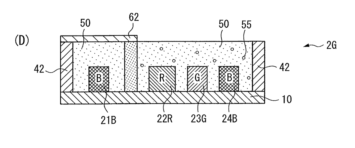
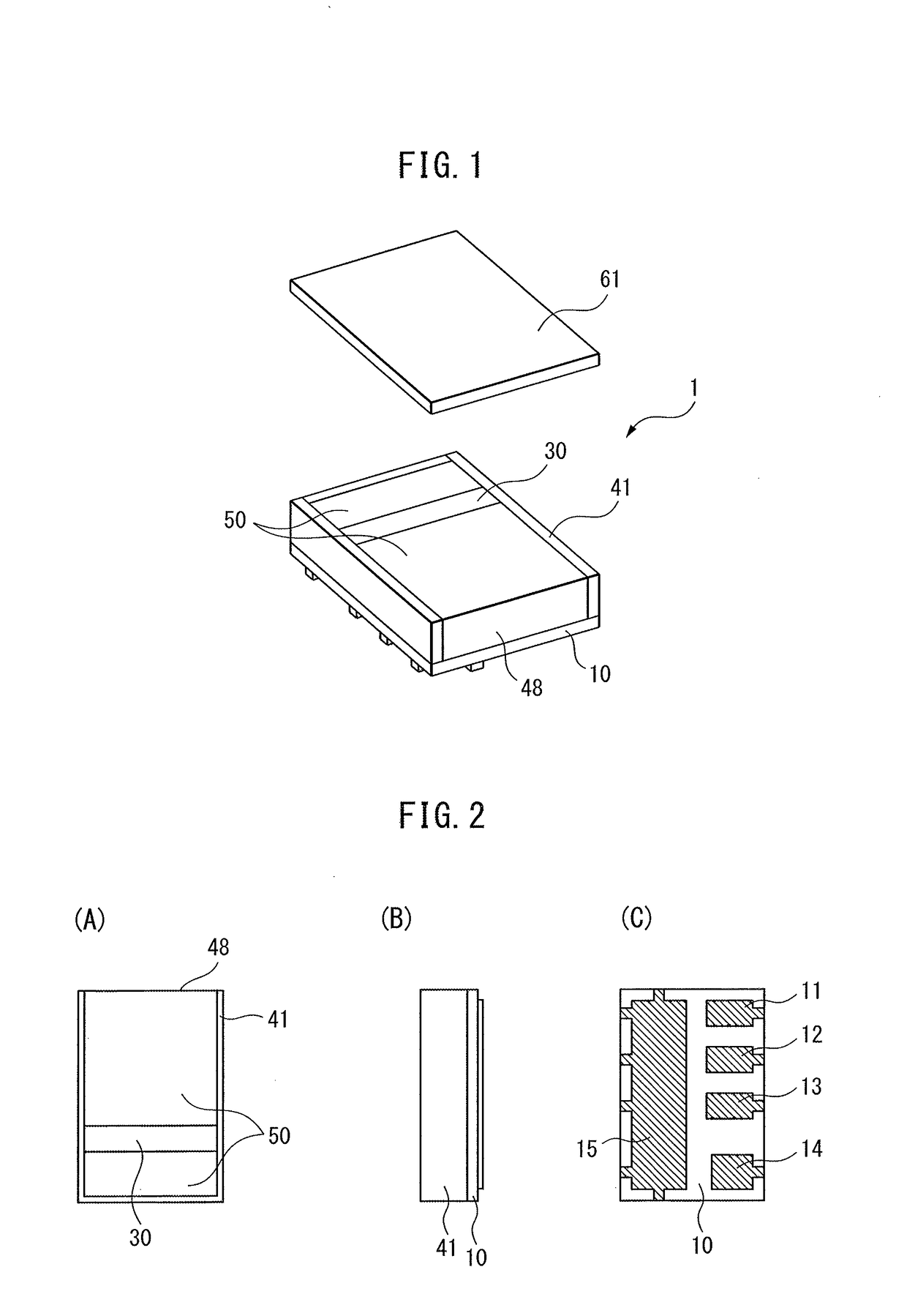
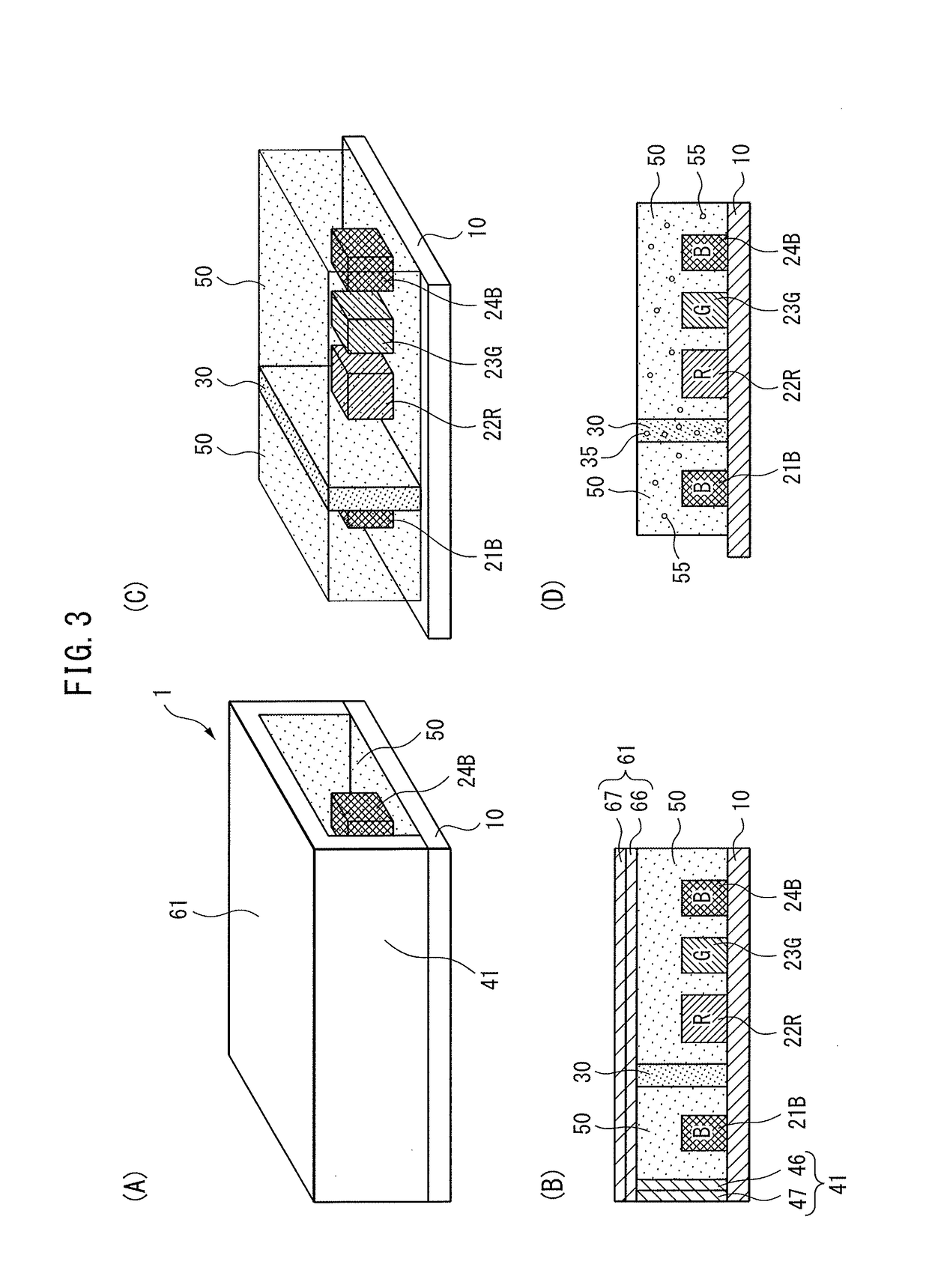
[0044]FIG. 1 is a perspective view of a light-emitting device 1. FIG. 2(A) to FIG. 2(C) are respectively a top view, a side view, and a bottom view of the light-emitting device 1. FIG. 3(A) to FIG. 4(B) are figures for illustrating the structure of the light-emitting device 1.

[0045]The light-emitting device 1 has a substrate 10, four LED elements 21B, 22R, 23G, and 24B, a phosphor layer 30, a resin frame 41, a sealing resin 50, and a light-shielding component 61. The light-emitting device 1 accomplishes white light with high color rendering performance by the three LED elements 22R, 23G, and 24B emitting respectively red (R) light, green (G) light, and blue (B) light, as well as the LED element 21B emitting white (W) light using the phosphor layer 30...


PUM


Abstract

A light-emitting device is provided whose color mixing property and light emission efficiency are improved, while white light with high color rendering performance is ensured by means of four kinds of LED elements emitting red, green, blue, and white light respectively. The light-emitting device includes a phosphor layer containing a phosphor, a first LED element to emit white light in combination with fluorescence generated by excitation of the phosphor, a second LED element to emit red light, a third LED element to emit green light, a fourth LED element to emit blue light placed more distant from the phosphor layer compared to the second and third LED elements, a substrate with the first to fourth LED elements mounted on a common mounting surface, a resin frame surrounding at least a part of an outer circumference of the substrate, a sealing resin injected inside the resin frame and on the substrate to encapsulate the first to fourth LED elements, and a light-shielding component placed on an upper surface of the sealing resin to cover at least the first LED element.

Description

CROSS REFERENCE TO RELATED APPLICATIONS[0001]This is the U.S. National Phase application of PCT / JP2016 / 077736, filed Sep. 20, 2016, which claims priority to Japanese Patent Application No. 2015-185976, filed Sep. 18, 2015, the disclosures of these applications being incorporated herein by reference in their entireties for all purposes.TECHNICAL FIELD OF THE INVENTION[0002]The present invention relates to a light-emitting device.BACKGROUND OF THE INVENTION[0003]Patent Literature 1 describes a light emitting diode chip provided with a green light-emitting element, a blue light-emitting element, and a red light-emitting element which are mounted as light emitters on a chip substrate, a reflection frame which is placed on the chip substrate so as to surround the light emitters and has an aperture at a part of an upper surface and a side wall, a reflection surface which is formed on an inner circumferential surface of a side wall of the reflection frame, an optically transparent resin bo...

Claims


Application Information

Patent Timeline
IPC IPC(8): H01L25/075H01L33/50H01L33/48H01L33/52H01L33/60
CPCH01L25/0753H01L33/505H01L33/483H01L33/52H01L33/60H01L33/507H01L2933/0091H01L2933/0033H01L2933/0041H01L2933/005H01L33/56G02B5/02
Inventor HAMADA, MASAHIKOISHII, HIROHIKO
Owner CITIZEN ELECTRONICS CO LTD
Learn More