

Cage for disc space between vertebrae
- Summary
- Abstract
- Description
- Claims
- Application Information
AI Technical Summary
Benefits of technology
Problems solved by technology
Method used
Image

Examples
Embodiment Construction
Problems to Solve
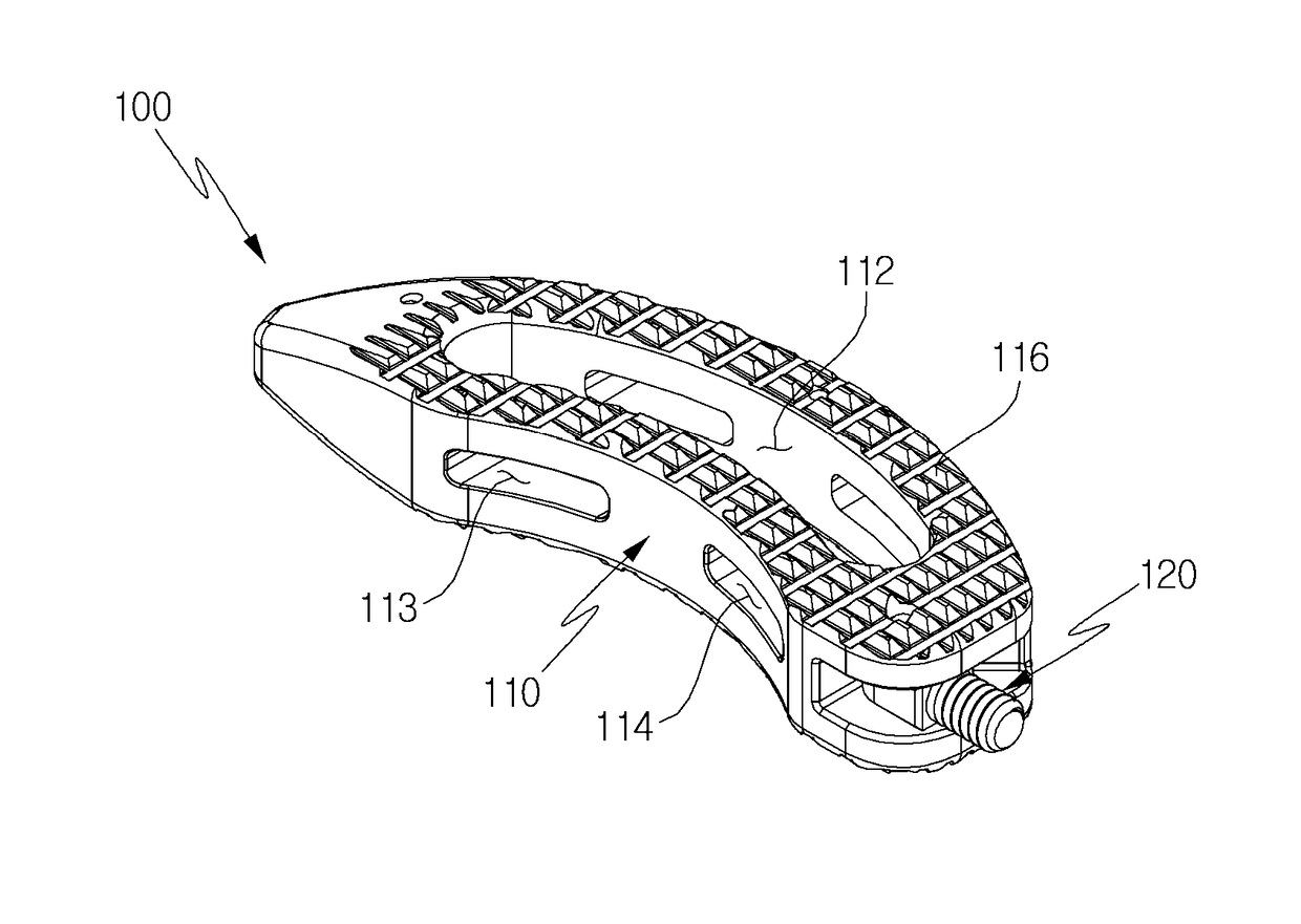
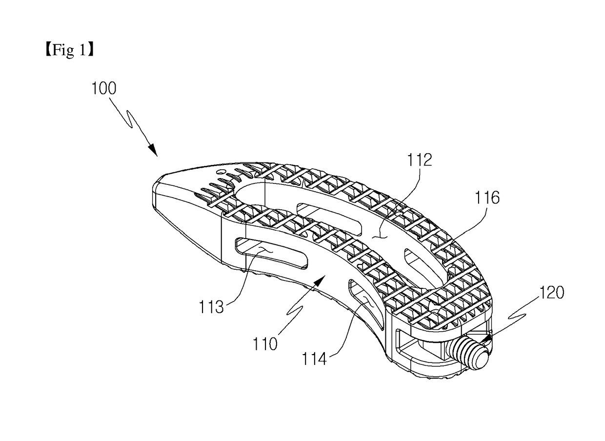
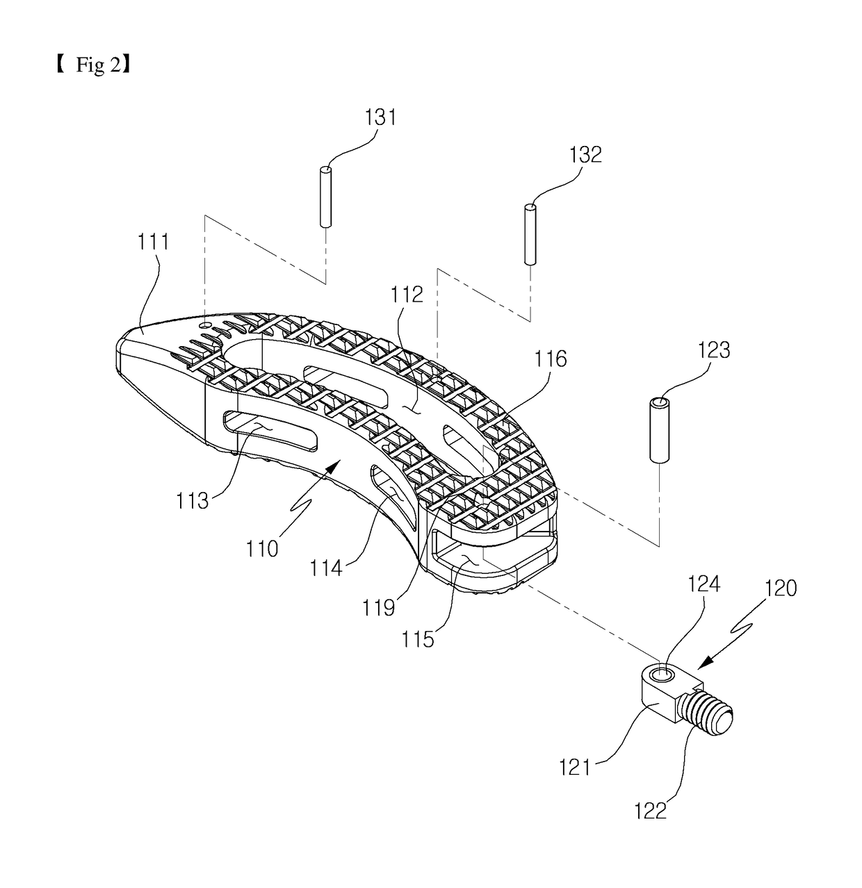
[0012]An object of the present invention is to provide a cage for a disc space between vertebrae which implements an articulated rotary motion and enhances coupling force with a cage inserting device to be stably inserted.
[0013]The technical objects of the present invention are not limited to the aforementioned technical objects, and other technical objects, which are not mentioned above, will be apparently appreciated by a person having ordinary skill in the art from the following description.
Solution for the Problems
[0014]In accordance with an embodiment of the present invention, disclosed is a cage for a disc space between vertebrae, including: a support unit inserted between vertebrae; a connection portion connected with the support unit, and a pivoting member including an insertion device connecting unit which extends from an end portion of the connection portion to protrude to the outside of the support unit and connected with an insertion device.
[0015]In acco...
PUM
 Abstract
Description
Claims
Application Information