Check patentability & draft patents in minutes with Patsnap Eureka AI!

Preform, a container, and a method for fabrication of a preform

a technology of preform and container, which is applied in the field of preform, can solve the problems of undesirable stresses in the preform material and molding apparatus, the method of fabricating preform known in the prior art, and the inability to meet the requirements of the preform material, and achieve the effect of better conformation

Inactive Publication Date: 2018-09-13
SOC DES PROD
View PDF1 Cites 0 Cited by
  • Summary
  • Abstract
  • Description
  • Claims
  • Application Information

AI Technical Summary

Benefits of technology

This invention relates to a method for making preforms that can be used to create containers. The method is advantageous because it allows for the optimization of each region of the preform based on the shape of the container it will become. This results in a more efficient use of material, reducing the cost and weight of the final container. The preform is designed in such a way that it is perfectly suited for the shape of the container, making it more cost-effective and suitable for various applications.

Problems solved by technology

The method of fabricating preforms known in the prior art is disadvantageous in several aspects.
First, the prior art process for fabricating preforms is disadvantageous in that it requires the preform to be of a minimum thickness, generally about 2 millimeters.
Injection molding components which have dimensions thinner than this induces undesirable stresses in the preform material and molding apparatus, and requires a higher injection pressure and greater injection time to complete the injection-molding process compared to components which respect this minimum.
This increased process time will render the use of injection molding economically infeasible for mass production of preforms in configurations which may be otherwise ideal.
In addition, the molten plastic may solidify prematurely if it is injected into a mold cavity feature thinner than this minimum thickness, preventing the entire mold cavity from being filled.
This method of fabricating preforms is therefore disadvantageous in that it does not permit the economical mass-production of preforms with walls which are not at least 2 millimeters thick.
Thus, in many cases preforms must be fabricated with more material than is strictly necessary to form the beverage container into which they will eventually be expanded, wasting material and increasing costs.
Second, the prior art process is disadvantageous in that the segment of the preform mold which defines the inside of the preform reduces the number of possible shapes that the preform may have.
If not, it will be impossible to extract said mold segment from the preform.
Thus, preforms which have a cross-section with an interior diameter greater than that of the open end may not be produced by the injection molding process.
This limits the possible geometries of the preforms, constraining their utility and, by extension, the flexibility and utility of the containers ultimately fabricated from those preforms.

Method used


Image

  • Preform, a container, and a method for fabrication of a preform
  • Preform, a container, and a method for fabrication of a preform
  • Preform, a container, and a method for fabrication of a preform

Examples


first embodiment

[0067]FIG. 1 depicts a preform according to the invention. In a first step for fabrication of the preform 100 of FIG. 1 a plurality of preform segments 101-103 are provided, each of which is substantially ring-shaped and defines a portion of the preform 100. In this embodiment, the preform 100 comprises a mouth segment 101, a body segment 102, and a tail segment 103. Preferably, the preform segments 101-103 are symmetric about a longitudinal axis 104 of the preform 100.

[0068]In a second step for fabrication of the preform 100, the preform segments 101-103 are positioned so as to be in continuous contact with each other along at least one edge of said preform segments 101-103. In this embodiment, an edge of the mouth segment 101 is in continuous contact with an edge of the body segment 102 along a first seam 105. A second edge of the body segment 102 is in continuous contact with an edge of the tail segment 103 at a second seam 106. The arrangement of the preform segments 101-103 in ...

third embodiment

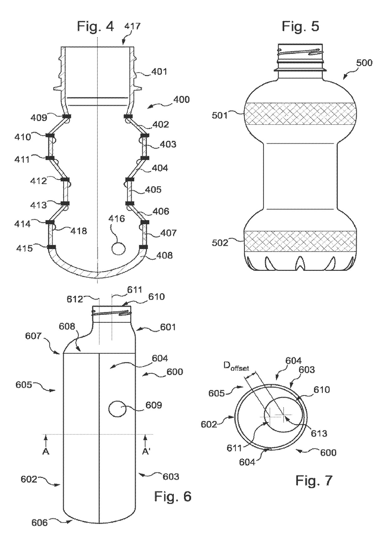
[0079]FIG. 4 depicts a preform according to the invention. The preform 400 is fabricated from eight preform segments 401-408, which are disposed in contact with each other as shown and bonded along their edges at several seams 409-415. The resultant preform 400 is thus provided with a cavity 416 in communication with an open end 417. The preform 400 is in a shape substantially resembling an hourglass, which when expanded will yield a substantially hourglass-shaped container.

[0080]The preform segments 401-408 are further provided with ribs 418 upon their internal surfaces. These ribs 418 serve to add additional structural strength and resistance to the container fabricated from the preform 400.

[0081]While FIG. 4 depicts an example of a preform in an hourglass shape, the method of the invention permits many other shapes, textures and contours to be realized in preforms, and by extension in containers. The invention thus offers a greatly increased variety of possible container shapes a...

fourth embodiment

[0084]FIG. 6 depicts a preform according to the invention.

[0085]The preform 600 is fabricated from three preform segments: a substantially ring-shaped neck segment 601, and two body segments 602 and 603. The body segments 602 and 603 are substantially identical, and are bonded along a longitudinal seam 604 to create a preform body 605 which is substantially tubular and closed at a first end 606. The neck segment 601 is bonded to the preform body 605 at a second end 607, along a circumferential seam 608, thereby producing the preform 600 which defines a cavity 609.

[0086]The neck segment 600 is provided with a mouth 610 with a centerline 611. The preform mouth centerline 611 is offset from the preform body centerline 612, which is shown in greater detail in Section A-A of FIG. 7.

[0087]FIG. 7 is a section view of the cavity 609 of the preform 600, looking towards the inside surface of the neck segment 601. The mouth 610 has a mouth center 613 which corresponds to the preform mouth cent...


PUM

PropertyMeasurementUnit
thicknessaaaaaaaaaa
thickaaaaaaaaaa
thicknessesaaaaaaaaaa

Abstract

A method for fabricating a preform by providing a plurality of preform segments which each define a portion of a preform, positioning said preform segments in continuous contact with each other along at least one edge of said preform segments such that said plurality of preform segments define a cavity, and bonding each of said preform segments to at least one other preform segment such that said plurality of preform segments forms a continuous whole.

Description

PRIORITY CLAIM[0001]This application is a divisional of U.S. application Ser. No. 14 / 414,756 filed Jan. 14, 2015, which is a National Stage of International Application No. PCT / EP13 / 065729 filed Jul. 25, 2013, which claims priority to European Application No. 12179128.9 filed Aug. 3, 2012, the entire contents of which are incorporated herein by reference.BACKGROUND[0002]This invention relates to a method for the fabrication of preforms notably for use in the fabrication of containers. In a general way, it concerns the fabrication of containers, and for instance beverage containers, from preforms. This invention further relates to a preform so produced by this method and a container which is fabricated therefrom.[0003]A well-known and commonly-employed technique in the art of fabricating containers is the method of blow-molding, wherein a mass of material is expanded to match the contours of a mold disposed about said mass. This is achieved by the injection of a working fluid, usuall...

Claims


Application Information

Patent Timeline
Patent Type & Authority Applications(United States)
IPC IPC(8): B32B37/24B65D1/40B65D1/02B29B11/04B29B11/14B29C65/08B29C65/00B32B37/00B32B37/06B32B37/18B29B11/08B29B11/10B29C49/00B29C49/02B29C49/12B29C65/48B29K23/00B29K67/00B29K105/00
CPCB29B11/10B29B11/04Y10T428/1397Y10T156/10B29K2995/0021B29K2105/258B29K2105/0094B29C2049/021B29C66/71B29C66/543B29C66/542B29C65/48B29C49/12B29C49/0078B29B2911/14573B29B2911/14433B29B2911/14373B29B2911/14353B29B2911/14333B29B2911/14326B29B2911/1448B29B2911/1434B29B2911/14013B32B37/24B29B11/08B65D1/40B65D1/0223B65D1/0207B32B37/18B32B37/06B32B37/0046B29C66/83221B29C66/81463B29C66/81423B29C66/81422B29C66/73921B29C66/63B29C66/612B29C66/5344B29C66/3452B29C66/131B29C66/1224B29C66/1222B29C65/08B29B11/14B32B2439/00B29K2067/003B29K2023/12B29C66/73122B29C2949/20B29C2949/074B29C2949/076B29C2949/0763B29C2949/0772B29C2949/073B29C2949/0779B29C2949/072B29C2949/08B29C49/071B29C2949/0715
Inventor CERVENY, JEAN-PAULDABROWSKI, NICOLASDETROIS, CHRISTIANLAINE, EMMANUELLUPKE, ERIK
Owner SOC DES PROD
Features
  • R&D
  • Intellectual Property
  • Life Sciences
  • Materials
  • Tech Scout
  • Unparalleled Data Quality
  • Higher Quality Content
  • 60% Fewer Hallucinations
Learn More