Printing System Having Individually Movable Sub-Detector Elements for Print Head Protection

Active Publication Date: 2018-09-13
SPGPRINTS
View PDF3 Cites 2 Cited by
  • Summary
  • Abstract
  • Description
  • Claims
  • Application Information

AI Technical Summary

Benefits of technology

The present invention is aimed at improving printing systems by providing better protection for vulnerable and expensive print heads against damage or crashes caused by obstacles. The goal is to offer a user-friendly and efficient printing system.

Problems solved by technology

When one or more of the light beams gets blocked by an obstruction that projects upwardly from the substrate, like for example a crumple in the substrate, then this causes the light sensors to sense shadow.
A disadvantage with this is that the functioning of the detection mechanism leaves to be improved.
This may lead to the light beams getting somewhat redirected and thus getting oriented to close above the substrate with the risk of running partly against the substrate, causing shadow on the light sensors and unnecessarily stopping the printing operation.
Even worse it may also occur that because of temperature changes the light beams get oriented too far above the substrate.
This may lead to a situation in which the light beams pass over an obstruction without being interrupted by it at all.
The printing operation then does not get stopped at all with the effect that the printheads may get damaged by such an undetected obstruction.
Another disadvantage is that it is difficult to accurately adjust the light beams and sensors relative to each other and relative to the substrate, in particular when large printing widths of several meters need to be covered.
Yet another disadvantage is that the detection mechanism requires free space at the opposing transverse sides of the substrate at the level of the substrate itself.
Because of that it is not possible to use light transmitters that get positioned so close to the substrate that they are able to transmit their light beams closely above the substrate during operation.
Such a swinging movement of the plate can be caused by the plate running against an obstruction on top of the substrate.
A disadvantage with this is that the high acceleration and deceleration forces that get exerted on the carriage during its high speed back and forth movements over the substrate, may accidentally induce a swinging movement of the plate and thus stop a printing operation without an obstruction being actually detected.
On the other hand it has also occurred that the plate, instead of being pushed away by an obstruction, started to press the obstruction into the substrate and thus damage the substrate, instead of sending out a detection signal towards the control unit that an emergency stop needed to be performed.
This however increased the risk of the plate starting to buckle when bumping against an obstruction, which buckling in turn stiffened the plate and thus increased the risk for malfunctioning of the detection mechanism.

Method used


Image

  • Printing System Having Individually Movable Sub-Detector Elements for Print Head Protection
  • Printing System Having Individually Movable Sub-Detector Elements for Print Head Protection
  • Printing System Having Individually Movable Sub-Detector Elements for Print Head Protection

Examples


Embodiment Construction

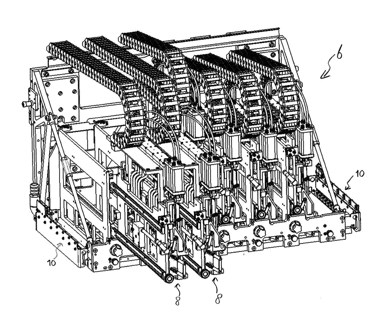
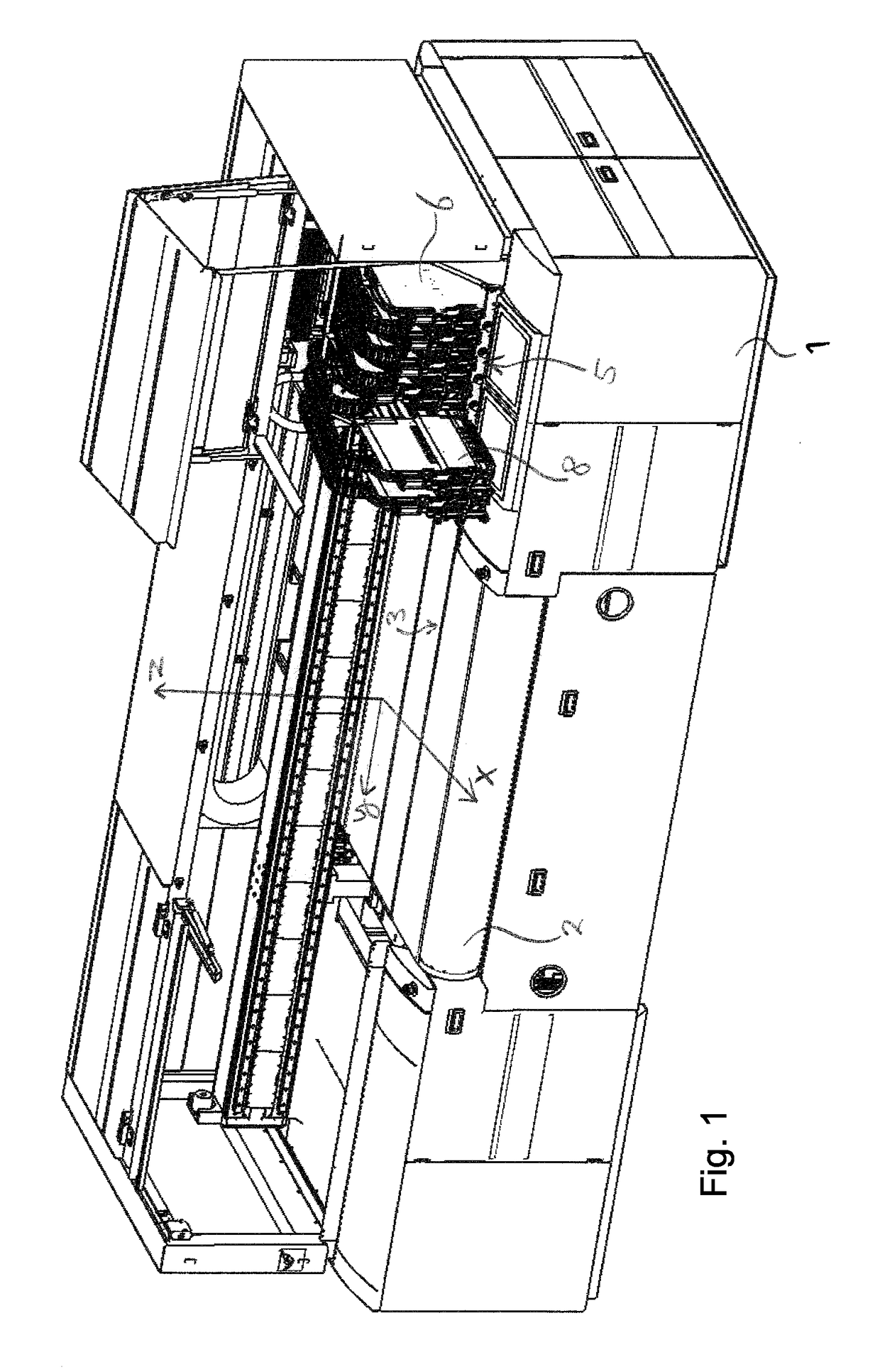
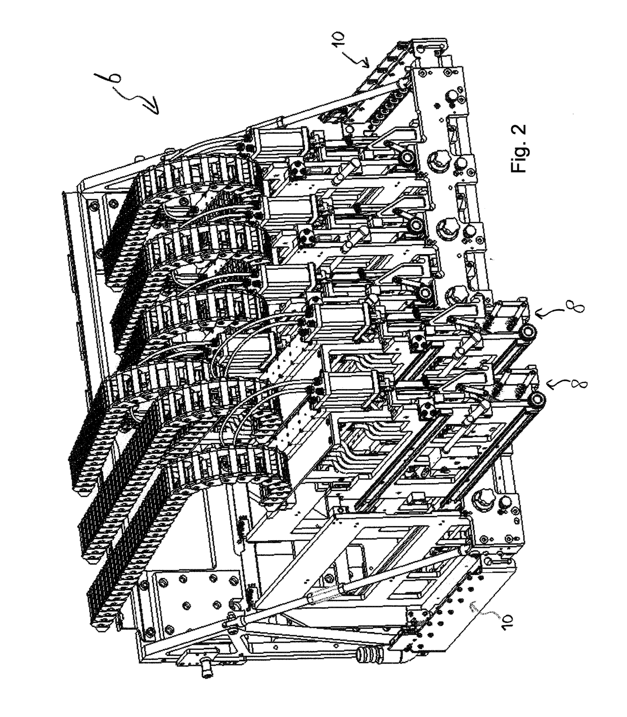
[0038]In FIG. 1 a scanning printing system is shown which has a main frame 1 that can be placed on the ground. The system comprises an operable conveyor belt as substrate holder 2 that is designed for supporting, holding and transporting a substrate 3 to be printed on. The substrate 3 is supported in a horizontal plane by the substrate holder 2 and can be moved by it in a transportation direction x. A sub-frame 5 forms a carriage 6 that is reciprocatingly movable in a transverse scanning direction y relative to the main frame 1 and the substrate 3. The x- and y-directions are perpendicular to each other. The carriage 6 holds six print modules 8 that are positioned adjacent each other in the y-direction. Each print module 8 is connected via a flexible duct to its own ink reservoir that is filled with its own distinctive colour and that is provided on the main frame 1. The print modules 8 are individually movable up and down in a vertical displacement direction z that is perpendicular...


PUM


Abstract

A printing system includes a print module with printheads covering a printing width in x-direction, and a substrate holder for supporting a substrate. The substrate and print module are movable relative to each other in y-direction. Each printhead is positioned spaced at a first distance from the substrate holder in z-direction. A detection mechanism is provided for detecting obstructions on the substrate holder. A control unit is provided for stopping further relative movement in the y-direction between the substrate and the print module when an obstruction has been detected. The detection mechanism includes individually movable sub-detection elements that together cover the printing width, where those elements are designed to have a detection signal send out to the control unit when one of the elements gets moved out of a starting position by an obstruction trying to pass it.

Description

FIELD OF THE INVENTION[0001]The invention relates to a printing system that is equipped with a detection mechanism for protection of printheads against damaging or even crashes that may be caused by obstructions, like crumples in a substrate to be printed, that might be too thick to pass underneath the printheads during a printing operation.BACKGROUND OF THE INVENTION[0002]From the state of the art numerous printing systems are known that, especially in industrial environments, often include some kind of automatic detection mechanism for detecting such obstructions and thus being able to properly protect the vulnerable and expensive printheads during operation.[0003]For example, single pass printing systems are known in which a plurality of print modules with print heads are placed next to each other such that they together cover a printing width in a transverse direction. During a printing operation, a substrate is moved stepwise underneath the print heads while being printed by th...

Claims


Application Information

Patent Timeline
IPC IPC(8): B41J2/045
CPCB41J2/04586B41J2/04505B41J2/1752B41J2/17536B41J29/02
Inventor MEULEMAN, PETER KLEINKUSTERS, SJEF
Owner SPGPRINTS
Why Eureka
Try Eureka