Vehicle control device and vehicle control system

a technology for vehicle control and control device, applied in the direction of fault response, instruments, transportation and packaging, etc., can solve the problems of increasing costs, and achieve the effect of ensuring safety after function substitution

Active Publication Date: 2018-09-13
HITACHI ASTEMO LTD
View PDF18 Cites 6 Cited by
  • Summary
  • Abstract
  • Description
  • Claims
  • Application Information

AI Technical Summary

Benefits of technology

[0010]According to a vehicle control device of the present invention, since the success or failure of a substituted function can be determined, the safety after function substitution can be secured.

Problems solved by technology

However, this method has a problem that cost increases because two ECUs must be prepared.

Method used


Image

  • Vehicle control device and vehicle control system
  • Vehicle control device and vehicle control system
  • Vehicle control device and vehicle control system

Examples


first embodiment

[0139]The vehicle control system 1 according to the first embodiment can determine whether the automatic parking ECU 13 has succeeded in the function substitution by comparing the control parameters before and after the start of substitution. Therefore, it is suitable for an automatic driving system which requires high reliability.

[0140]In the vehicle control system 1 according to the first embodiment, since the functions are made redundant by the function substitution between the ECUs, there is no need to make the ECU body redundant. Therefore, a highly reliable system can be constructed at a low cost.

second embodiment

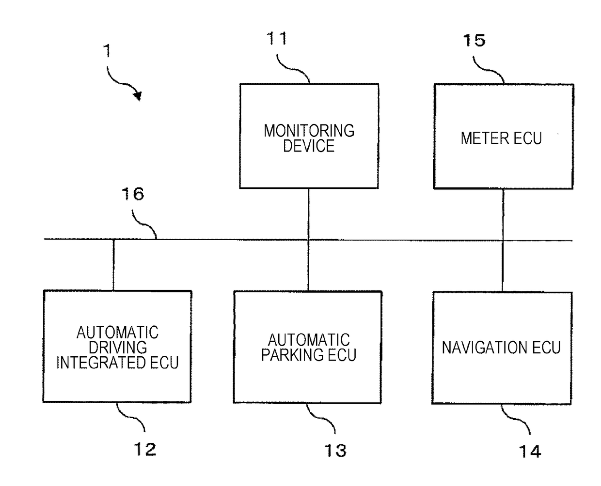
[0141]FIG. 31 is a configuration diagram of a vehicle control system 1 according to a second embodiment of the present invention. A gateway 21 includes a monitoring unit 211 having the same configuration as the monitoring device 11 described in the first embodiment and has a role of relaying communication in an in-vehicle network.

[0142]In the second embodiment, a meter ECU 15 and a navigation ECU 14 are connected to an in-vehicle network 16, an automatic driving integrated ECU 12 is connected to an in-vehicle network 22, and an automatic parking ECU 13 is connected to an in-vehicle network 23. Each in-vehicle network is connected through a gateway 21, and the gateway 21 can mutually communicate by relaying communication data. The in-vehicle network 22 and the in-vehicle network 23 are one-to-one communication networks such as Ethernet (registered trademark).

[0143]When it is determined that the automatic parking ECU 13 has failed in the function substitution, the gateway 21 may not t...

third embodiment

[0146]FIG. 32 is a configuration diagram of a vehicle control system 1 according to a third embodiment of the present invention. In the third embodiment, an automatic parking ECU 13 includes an automatic parking microcomputer 136 and a monitoring microcomputer 137. These microcomputers are connected by, for example, a serial line.

[0147]The automatic parking microcomputer 136 is a microcomputer having the same function as that of the automatic parking ECU 13 described in the first embodiment. The monitoring microcomputer 137 is a microcomputer having the same function as that of the monitoring device 11 described in the first embodiment.

[0148]In the vehicle control system 1 according to the third embodiment, since the monitoring microcomputer 137 is provided in the automatic parking ECU 13 to realize the same function as that of the monitoring device 11, it is possible to realize the equivalent function at a lower cost than constructing the monitoring device 11 as an independent ECU....


PUM


Abstract

The purpose of the present invention is to provide a vehicle control technique that enables the safety of function substitution to be increased. This vehicle control device determines whether a substitution was successful by monitoring the operations which follow initiation of the substitution.

Description

TECHNICAL FIELD[0001]The present invention relates to a technology for controlling a vehicle.BACKGROUND ART[0002]In recent years, many vehicle control systems include an electronic control unit (ECU) which operates electronic vehicle control instruments, and an in-vehicle network (local area network) which enables communication between ECUs.[0003]In addition, in recent years, there has been an increasing demand for an automatic driving system which automatically carries a vehicle to a destination, without a driver's access, brake, or steering operation. In the automatic driving system, it is necessary to ensure sufficient safety even when an automatic driving integrated ECU which takes over the driver's determination fails. Which state is safe depends on a driving environment. For example, it can be said that it is safe to keep driving without stopping in harsh environments such as expressways or extreme cold areas.[0004]Redundancy of functions is known as a method for keeping an au...

Claims


Application Information

Patent Timeline
Patent Type & Authority Applications(United States)
IPC IPC(8): B60W50/029B60W50/023B60W30/06B60W50/14B60R16/023
CPCB60W50/029B60W50/023B60W30/06B60W50/14B60R16/0231B60R16/023G08G1/00H04L12/28G06F11/0739G06F11/0793G06F11/2028G06F11/2035
Inventor ISHIGOOKA, TASUKUOTSUKA, SATOSHISAKURAI, KOHEI
Owner HITACHI ASTEMO LTD
Why Eureka
Try Eureka