Rear body structure

a rear body and body technology, applied in the direction of superstructure connections, superstructure subunits, belt anchoring devices, etc., can solve problems such as bad design faces, and achieve the effects of simple structure, improved rigidity, and sufficient rigidity

Active Publication Date: 2018-09-20
HONDA MOTOR CO LTD
View PDF26 Cites 9 Cited by
  • Summary
  • Abstract
  • Description
  • Claims
  • Application Information

AI Technical Summary

Benefits of technology

[0012]According to the present invention, the design face of the rear pillar looks nice and the rear pillar has sufficient rigidity. In addition, according to the present invention, the corner of the rear pillar has imp

Problems solved by technology

Therefore, mounting marks of the reinforcing member on the inner face of the outer memb

Method used


Image

  • Rear body structure
  • Rear body structure
  • Rear body structure

Examples


Embodiment Construction

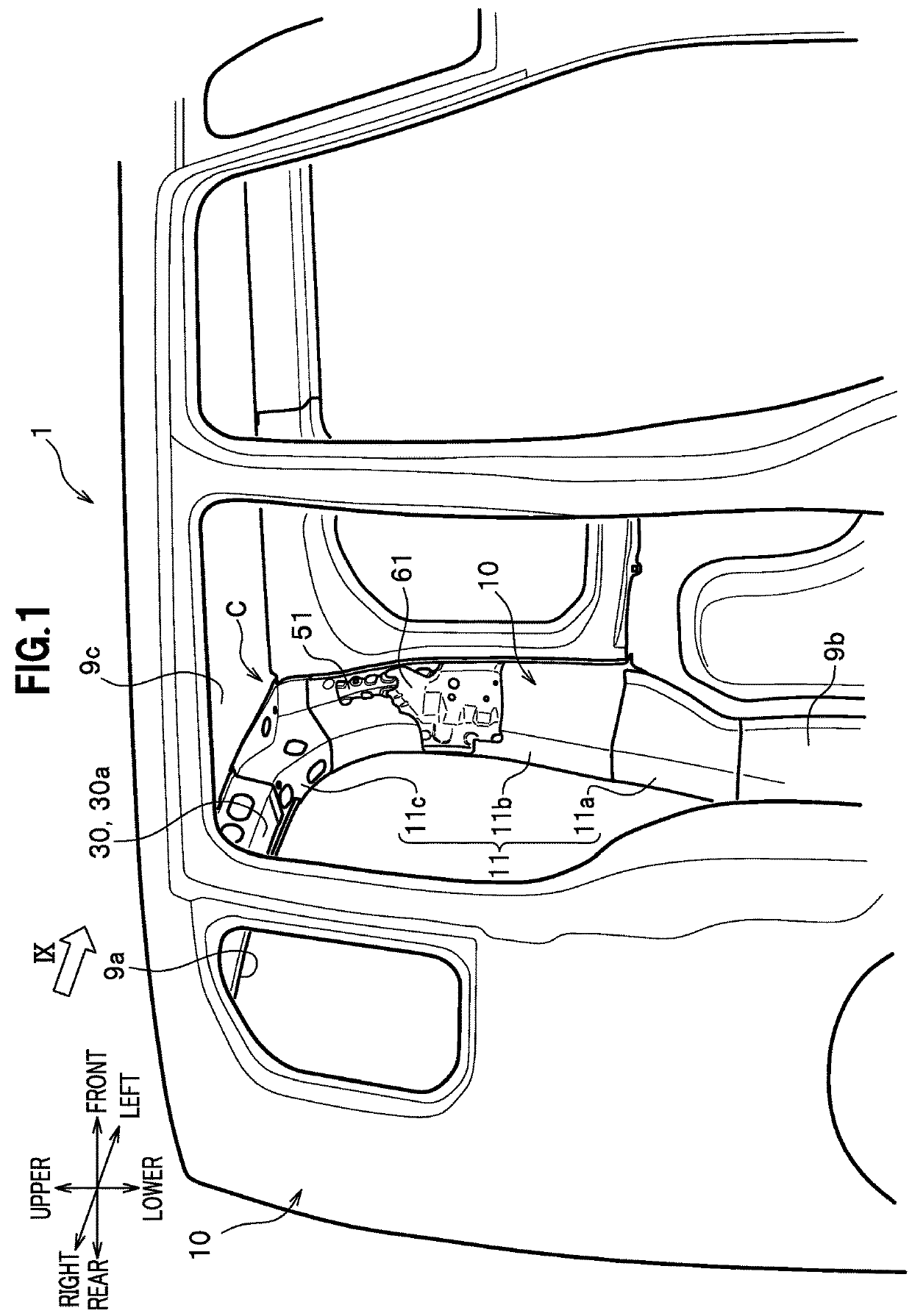
[0026]Next, an embodiment (present embodiment) of the present invention will be described in detail. A rear body structure in the present embodiment is provided with rear pillars at the rear of a vehicle. In the following description of the rear body structure, the longitudinal, lateral and vertical directions are as viewed from a driver sitting in the vehicle, and the directions shown in FIG. 1 are used throughout all the drawings. FIG. 1 is a perspective view of a rear body structure 1 according to the present embodiment. Specifically, FIG. 1 is a perspective view of the rear body structure 1 having a rear pillar 10, as viewed diagonally from the front at the right side of the vehicle toward the interior of the vehicle through an opening of a rear door at the right side. Note that, in the drawings referred to in the following description, a door attached to the vehicle and a garnish attached inside the vehicle are not shown for the purpose of illustration.

[0027]As shown in FIG. 1,...


PUM


Abstract

A rear body structure is provided that forms a design face of a rear pillar nicely and gives sufficient rigidity to the rear pillar. The rear body structure has a rear pillar at a rear of a vehicle body. The rear pillar includes an outer rear pillar that is arranged on an outside in a lateral direction to form an exterior face of the rear pillar, and an inner rear pillar that is arranged inside in the lateral direction of the outer rear pillar. The inner rear pillar has a protrusion that protrudes toward the outer rear pillar. The protrusion is formed continuously in a vertical direction of the rear pillar.

Description

CROSS-REFERENCE TO RELATED APPLICATION[0001]This application claims the benefit of priority to Japanese Patent Application Nos. 2017-47951, 2017-48403 and 2017-48220 filed on Mar. 14, 2017, the disclosures of all of which are hereby incorporated by reference in their entireties.FIELD OF THE INVENTION[0002]The present invention relates to a rear body structure having rear pillars.DESCRIPTION OF THE RELATED ART[0003]A conventional rear pillar of a car is known to have an outer member arranged outside a vehicle and an inner member arranged inside the vehicle so as to be joined to each other to form hollow portions having a closed cross section (see Japanese Patent Application Publication No. 2014-169046, for example). In a rear body structure having such a rear pillar, a reinforcing member, for example, in a U-shape may be attached, such as by spot-welding, on an inner side face of the outer member, to increase face rigidity of the outer members. Further, in a rear body structure havin...

Claims


Application Information

Patent Timeline
IPC IPC(8): B62D25/04B62D25/06B62D27/02B60R22/24B62D25/02
CPCB62D25/04B62D25/06B62D27/023B60R22/24B62D25/02
Inventor NAKAYAMA, MANABUOHKI, YUKIHIRO
Owner HONDA MOTOR CO LTD
Why Eureka
Try Eureka