Transmitter For Wireless Charger

Active Publication Date: 2018-09-20
AMOSENSE
View PDF3 Cites 9 Cited by
  • Summary
  • Abstract
  • Description
  • Claims
  • Application Information

AI Technical Summary

Benefits of technology

[0023]According to the embodiments of the present invention, a transmission device for a wireless charger may provide a plurality of planar coils having the same efficiency by removing

Problems solved by technology

However, there is present a difficulty in connecting connectors according to charging a battery that is a power source using a wired charger.
However, during a process of mechanically twisting or bending the planar coil, the planar coil is damaged and a defective occurs.
Addition

Method used


Image

  • Transmitter For Wireless Charger
  • Transmitter For Wireless Charger
  • Transmitter For Wireless Charger

Examples


Embodiment Construction

[0034]Hereinafter, embodiments of the present invention will be described in detail with reference to the attached drawings to allow one of ordinary skill in the art to easily implement. The present invention may be embodied in several various forms and is not limited to the embodiments described herein. In the drawings, to definitely describe the present invention, parts irrelevant to the description are omitted. Throughout the drawings, like reference numerals refer to like elements.

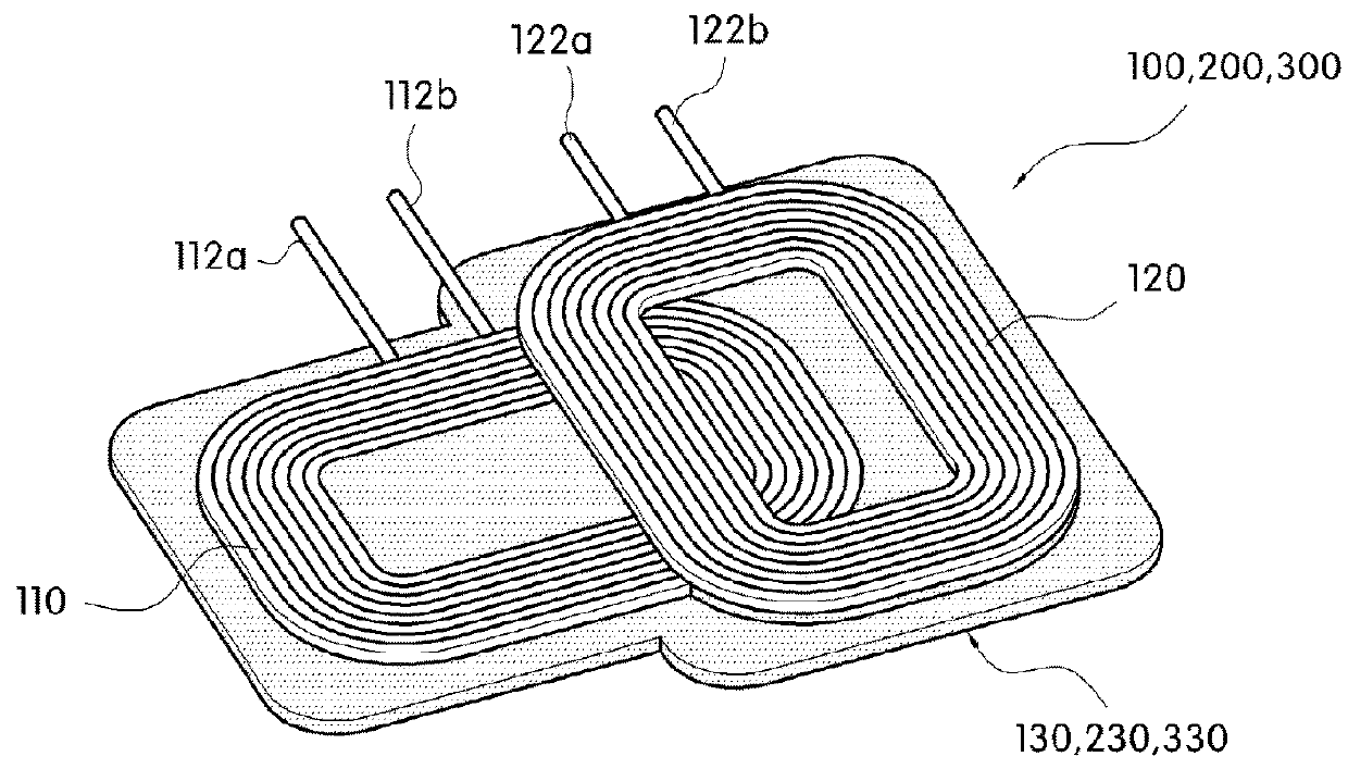
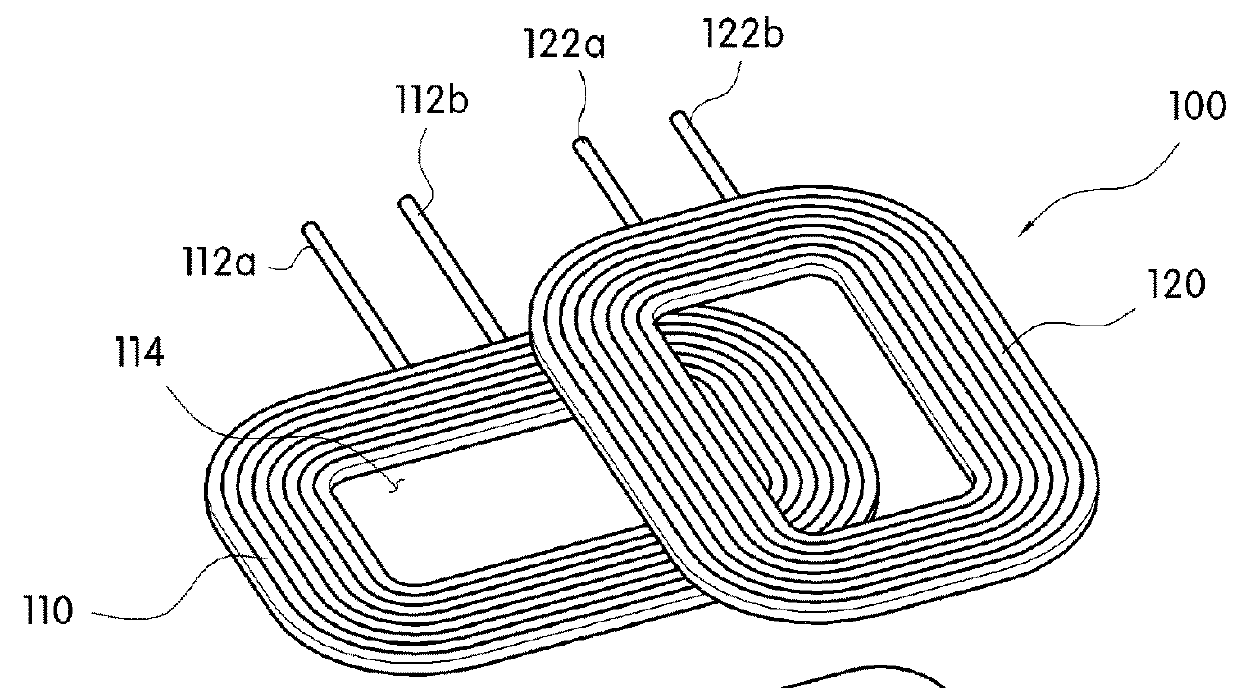
[0035]Referring to FIGS. 2 to 9, transmission devices 100, 100′, 200, and 200′ for a wireless charger according to embodiments of the present invention include planar coils 110 and 120, shielding sheets 130, 230, or 330, and a height deviation compensation means.

[0036]The planar coils 110 and 120 transmit a wireless power signal to a portable electronic device such as a cellular phone, a PDA, a PMP, a tablet, a multimedia device and the like to transfer power needed by the portable electronic device an...


PUM


Abstract

Provided is a transmission device for a wireless charger. A transmission device for a wireless charger in accordance with exemplary embodiments of the present invention comprises: a plurality of planar coils which transmit a wireless power signal for wireless charging and which are arranged so as to be at least partially overlapped with each other; a shielding sheet which has an attachment surface to which a part or all of the planar coils are fixed by the medium of an adhesive layer, and which shields a magnetic field generated from the planar coils; and a height deviation compensation means which is provided on the attachment surface and which compensates for individual height deviation between each planar coil and the attachment surface.

Description

TECHNICAL FIELD[0001]The present invention relates to a transmission device for a wireless charger, and more particularly, to a transmission device for a wireless charger, capable of preventing efficiency from being decreased due to an arrangement position of a planar coil.BACKGROUND ART[0002]There are a contact type charging method and a noncontact type charging method in methods of charging a secondary battery mounted in an electronic device such as a portable terminal, a video camera, and the like. The contact type charging method performs charging by allowing an electrode of a power receiving apparatus and an electrode of a power feeding apparatus to come into contact with each other.[0003]Due to a simple device-structure thereof, the contact type charging method is generally used in various application fields. However, there is present a difficulty in connecting connectors according to charging a battery that is a power source using a wired charger.[0004]To solve this, the nonc...

Claims


Application Information

Patent Timeline
IPC IPC(8): H02J50/10H01F27/36H02J50/40H02J7/02H02J50/70
CPCH02J50/10H01F27/36H02J50/40H02J7/025H02J50/70H01F38/14H01F27/366H01F27/306H02J50/005H05K9/0075
Inventor JANG, KIL JAELEE, DONG HOONJANG, MIN SIKKIM, KI CHULPARK, JONG HO
Owner AMOSENSE
Why Eureka
Try Eureka