Hydrodynamic clutch device with a transmission

a technology of hydraulic clutch and transmission, which is applied in the direction of fluid gearing, belt/chain/gearing, differential gearing, etc., can solve the problems of high construction cost, poor efficiency of the adaptation of the clutch device in this way,

Inactive Publication Date: 2000-12-05
MANNESMANN SACHS AG
View PDF8 Cites 6 Cited by
  • Summary
  • Abstract
  • Description
  • Claims
  • Application Information

AI Technical Summary

Problems solved by technology

The drawback in adapting the clutch device in this way is a comparatively poor efficiency because, due to the unchangeability of the characteristic of the clu

Method used


Image

  • Hydrodynamic clutch device with a transmission
  • Hydrodynamic clutch device with a transmission
  • Hydrodynamic clutch device with a transmission

Examples


Embodiment Construction

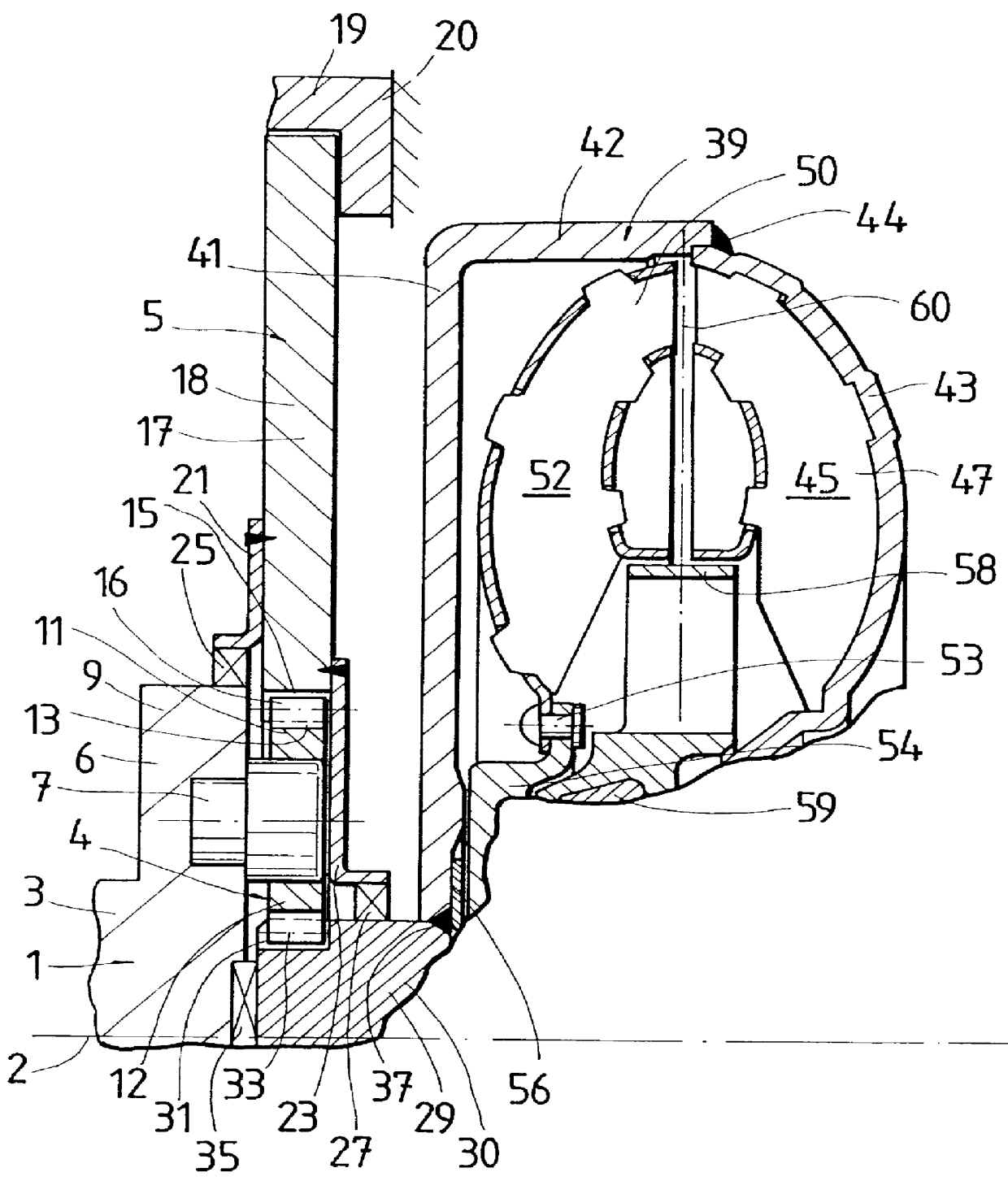
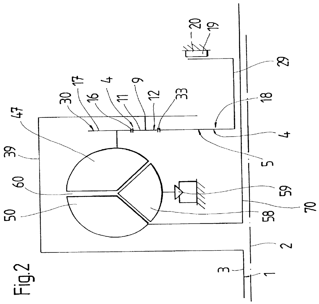
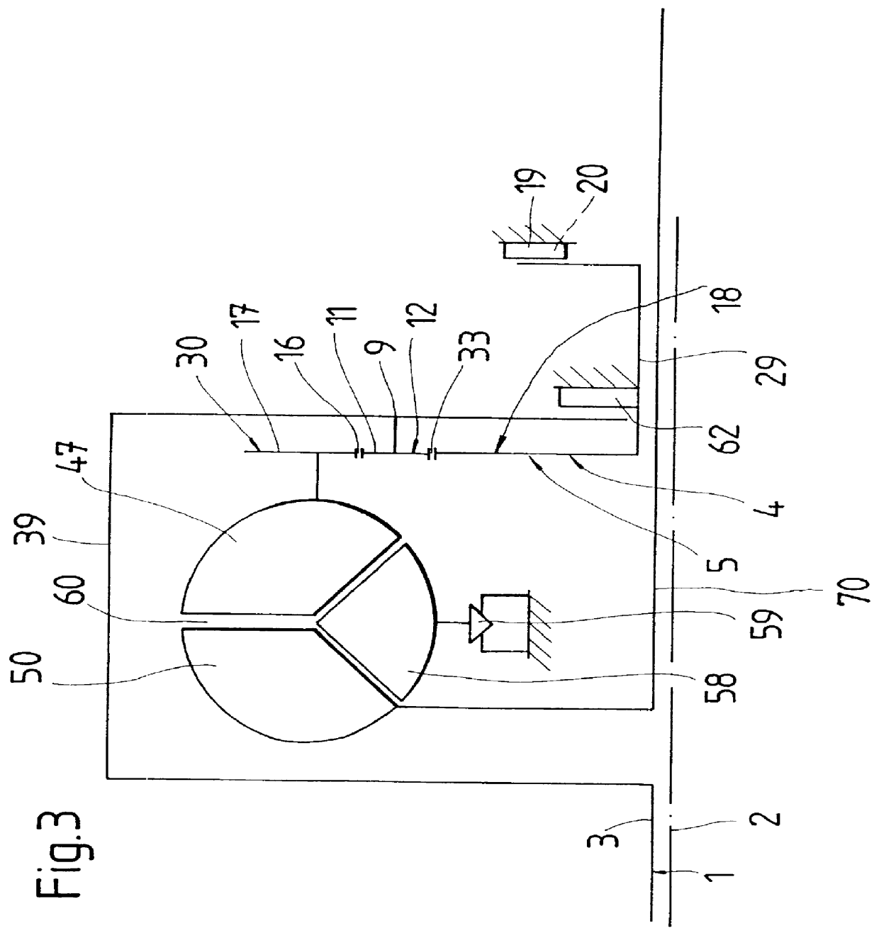
FIG. 1 shows a clutch device formed by a hydrodynamic torque converter which is connected to a drive 1 in the form of the crankshaft 3 of an internal combustion engine. The clutch device, like the crankshaft 3, is rotatable about an axis of rotation 2. The torque converter is connected, via a gear unit 4, with the crankshaft 3, namely, in this special case of construction, via a planetary gearset 5 which, as will be explained more fully in the following, has planetary gears 11, a ring gear 17 radially arranged outside of the planetary gears 11 and a sun gear 29 which is provided radially inside of the planetary gears 11. The planetary gears 11 have teeth 13, each of which forms a tooth engagement 16 with a toothing 15 of the ring gear 17 and a tooth engagement 33 with a toothing 31 of the sun gear 29. The planetary wheels 11 are arranged so as to be rotatable in each instance via a bearing neck 7 in a flange 6 of the crankshaft 3, so that the crankshaft 3 acts as a planetary carrier...


PUM


Abstract

A hydrodynamic clutch device is constructed with a clutch housing which is in a working connection with at least one drive. The hydrodynamic, clutch device has a hydrodynamic circuit formed at least by an impeller wheel and turbine wheel. The speed of the impeller wheel is adjustable corresponding to the speed of the housing, and the drive is connected with the impeller wheel via a transmission for carrying out a change in the speed.

Description

1. Field of the InventionThe present invention relates to hydrodynamic clutch devices and more particularly to a hydrodynamic clutch device having a transmission.2. Description of the Related ArtDE 44 23 640 A1 describes, particularly in FIG. 1, a hydrodynamic clutch device in the form of a torque converter having a clutch housing which can be brought into working connection with a drive, for example, the crankshaft of an internal combustion engine. The torque converter has an impeller wheel, a turbine wheel and stator wheel axially arranged between the impeller wheel and the turbine wheel thereby forming a hydrodynamic circuit, wherein the stator wheel is arranged on a stator freewheel.The above-mentioned working connection between the drive and a clutch housing can be seen, for example, from DE 32 22 119 C1, FIG. 1. In this case, where the crankshaft serves as a drive, the clutch housing is screwed thereto via a plate. Consequently, because of the fixed connection with respect to ...

Claims


Application Information

Patent Timeline
IPC IPC(8): F16H45/02F16H47/08F16H45/00F16H47/00
CPCF16H45/00F16H45/02F16H47/08Y10T74/19158F16H2045/002F16H2045/0268F16H2041/246
Inventor SUDAU, JORG
Owner MANNESMANN SACHS AG
Why Eureka
Try Eureka