
Eureka
For R&D, Eureka makes reading and utilizing patents & technical documents easy.
Eureka AIR
Designed for self-driven R&D workflows. Generate viable solutions, solve complex R&D challenges, empower your innovation with AI.

Eureka Materials
Designed for material experts only. Revolutionize your material R&D, from search, analyze, to developing new materials.

TechResearch
Generate reliable direction feasibility study reports for your R&D in just a few steps.

TechSeek
Discover and master advanced knowledge NOW. Basics, ideas, possibilities, all at once.

TechMind
As an expert in R&D Theories, TechMind can generates customized viable solutions instantly.

TechRisk
Analyze your overall solution with one click, know your potential R&D risks in advance.

TechMonitor
Get weekly tech updates, stay abreast of the latest tech innovations and key insights.
Magnetic sensor
- Summary
- Abstract
- Description
- Claims
- Application Information
AI Technical Summary
Benefits of technology
Problems solved by technology
Method used
Image

Examples
first embodiment
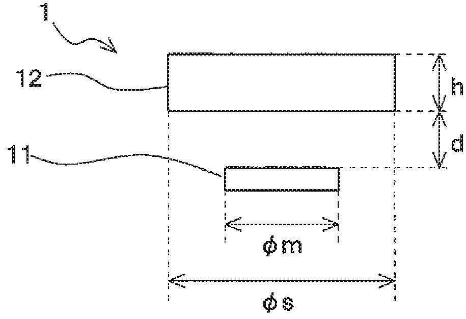
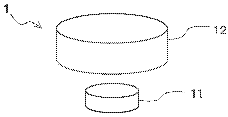
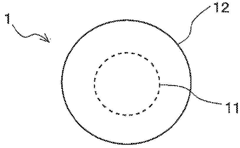
[0061]FIG. 1A is a schematic perspective view showing a magnetic sensor 1 relating to a first embodiment of the present invention; FIG. 1B is a schematic side view showing the magnetic sensor 1 relating to the first embodiment of the present invention; and FIG. 1C is a schematic plan view showing the magnetic sensor 1 relating to the first embodiment of the present invention. The magnetic sensor 1 is used for detecting a rotation angle due to relative movement of a rotor or the like and a linear displacement or the like of an object. For example, a magnet as a magnetic field generating part is placed in a rotating body, which is an object for detection of a rotation angle, and the magnetic field generating part generates the magnetic field to be detected. When the magnetic sensor 1 which is incorporated into a rotation angle sensor is used, the magnetic sensor 1 produces an angle detection value having a correspondence relationship with the angle between the direction of the magneti...
second embodiment
[0098]FIG. 8A is an entire schematic perspective view showing the magnetic sensor 1 relating to the second embodiment of the present invention, and FIG. 8B is a schematic side view showing the magnetic sensor 1 relating to the second embodiment of the present invention. Furthermore, the configuration that is nearly similar to that of the magnetic sensor 1 in the first embodiment is marked with the same symbols and its detailed explanation is omitted.
[0099]As shown in FIG. 8A and FIG. 8B, the soft magnetic body shield 12 configuring the magnetic sensor 1 relating to the second embodiment has a hexagonal-column shape. Furthermore, the shape of the soft magnetic body shield 12 configuring the magnetic sensor 1 is not limited to the hexagonal-column shape, but any shape is acceptable as long as the shape is a polygonal column with N sides (N is 6 or greater even number) of its plan view shape, such as an octagonal pillar, a dodecagonal pillar or a hexadecagonal pillar. Further, it is pr...
third embodiment
[0101]FIG. 9A is an entire schematic perspective view showing the magnetic sensor 1 relating to the third embodiment of the present invention, and FIG. 9B is a schematic side view showing the magnetic sensor 1 relating to the third embodiment of the present invention. Furthermore, the configuration that is nearly similar to that of the magnetic sensor 1 in the first embodiment is marked with the same symbols and its detailed explanation is omitted.
[0102]As shown in FIG. 9A and FIG. 9B, the soft magnetic body shield 12 configuring the magnetic sensor 1 relating to the third embodiment has shape in which a conical portion 12p is positioned on a columnar portion 12c that is circular in a plan view. The shape of the soft magnetic body shield 12 is not limited to the shape above, but can be a shape having a convexity where at least a portion of the upper surface of the columnar portion 12c protrudes. As the shape of the soft magnetic body shield 12, for example, a shape can be appropriat...
PUM
 Abstract
Description
Claims
Application Information
 - R&D Engineer
- R&D Manager
- IP Professional
- Industry Leading Data Capabilities
- Powerful AI technology
- Patent DNA Extraction
Browse by: Latest US Patents, China's latest patents, Technical Efficacy Thesaurus, Application Domain, Technology Topic, Popular Technical Reports.
© 2024 PatSnap. All rights reserved.Legal|Privacy policy|Modern Slavery Act Transparency Statement|Sitemap|About US| Contact US: help@patsnap.com