

Magnetoresistive effect element, magnetic memory cell using same, and random access memory
a technology of magnetic memory cell and effect element, applied in the direction of solid-state devices, magnetic bodies, instruments, etc., can solve the problem of thermal stability of magnetic information in the mtj element, and achieve the effect of high tmr ratio
- Summary
- Abstract
- Description
- Claims
- Application Information
AI Technical Summary
Benefits of technology
Problems solved by technology
Method used
Image

Examples
example 1
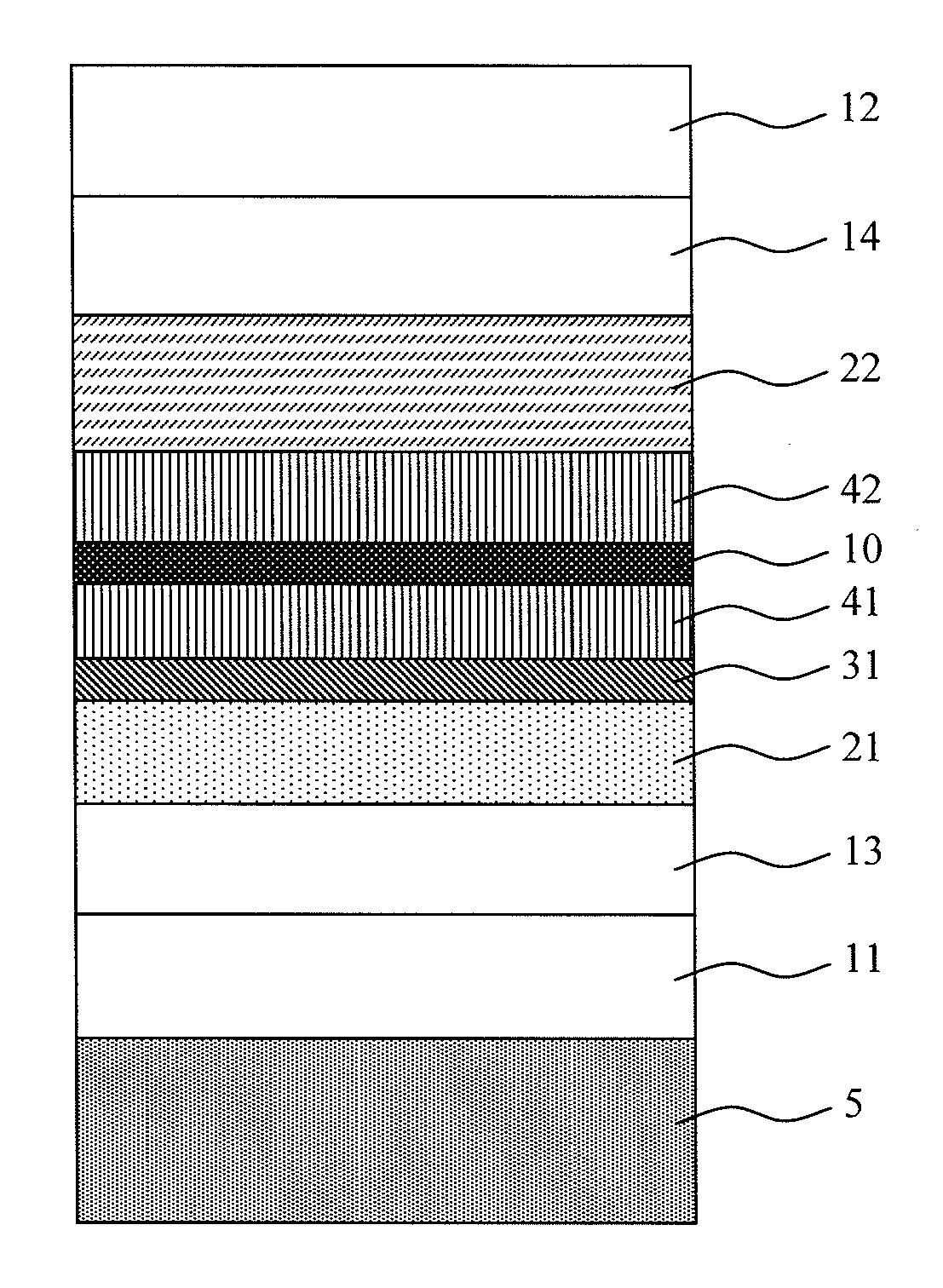
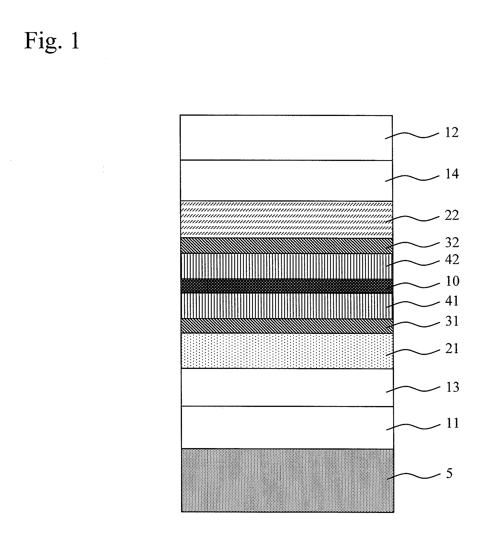
[0026]FIG. 1 shows a cross-sectional schematic diagram of an MTJ element according to Example 1. A first high polarizability magnetic layer 41 and a second high polarizability magnetic layer 42, which have a high electron spin polarizability, are disposed on both sides of a barrier layer 10. On the outside thereof, a first intermediate layer 31 and a second intermediate layer 32 are disposed, and a first magnetic layer 21 and a second magnetic layer 22 are disposed to be respectively adjacent to these layers. Further, on the lower side of the first magnetic layer 21, a lower electrode 11 and a foundation layer 13 are formed, and on the upper side of the second magnetic layer 22, a cap layer 14 and an upper electrode 12 are formed.
[0027]As materials of each layer, MgO (film thickness: 1 nm) was used as the barrier layer 10; a multi-layer film (film thickness: 14 nm) formed by laminating a two-layer film of CoFe (film thickness: 0.2 nm) and Pd (film thickness: 1.2 nm) by 10 cycles was...
example 2
[0039]Example 2 proposes an MTJ element in which a laminate structure of a perpendicularly magnetized magnetic layer, an intermediate layer, and a high polarization magnetic layer is applied only to the lower side of the barrier layer 10. FIG. 4 shows a cross-sectional schematic diagram of the MTJ element of Example 2. The basic structure is similar to that of the element illustrated in Example 1. However, in Example 2, the second magnetic layer 22 showing perpendicular magnetization is connected in direct contact with the second high polarizability magnetic layer 42, and no intermediate layer is inserted therebetween.
[0040]As materials of each layer, MgO (film thickness: 1 nm) was used for the barrier layer 10; a multi-layer film (film thickness: 14 nm) formed by laminating a two-layer film of CoFe (film thickness: 0.2 nm) and Pd (film thickness: 1.2 nm) by 10 cycles was used for the first magnetic layer 21; and a multi-layer film (film thickness: 4.2 nm) formed by laminating a two...
example 3
[0050]Example 3 proposes an MTJ element in which a laminate structure of a perpendicularly magnetized magnetic layer, a high polarizability magnetic layer, an intermediate layer, and a high polarizability magnetic layer is applied to the lower side of the barrier layer. FIG. 5 shows a cross-sectional schematic diagram of the MTJ element of Example 3. The basic structure is similar to that of the element illustrated in Example 1, except that a third high polarizability magnetic layer 43 is inserted between the first intermediate layer 31 and the first magnetic layer 21.
[0051]As materials of each layer, MgO (film thickness: 1 nm) was used for the barrier layer 10; a multi-layer film (film thickness: 14 nm) formed by laminating a two-layer film of CoFe (film thickness: 0.2 nm) and Pd (film thickness: 1.2 nm) by 10 cycles was used for the first magnetic layer 21; and a multi-layer film (film thickness: 4.2 nm) formed by laminating a two-layer film of CoFe (film thickness: 0.2 nm) and Pd...
PUM
| Property | Measurement | Unit |
|---|---|---|
| thickness | aaaaa | aaaaa |
| thickness | aaaaa | aaaaa |
| thickness | aaaaa | aaaaa |
Abstract
Description
Claims
Application Information