Liquid ejecting apparatus and liquid ejection method

a technology of liquid ejecting apparatus and liquid ejection method, which is applied in the direction of printing and inking apparatus, etc., can solve the problem of leakage of ink through the nozzl

Active Publication Date: 2018-10-04
SEIKO EPSON CORP
View PDF3 Cites 2 Cited by
  • Summary
  • Abstract
  • Description
  • Claims
  • Application Information

AI Technical Summary

Benefits of technology

[0004]An advantage of some aspects of the invention is that at least some of the above

Problems solved by technology

However, according to the technique described in JP-A-2011-213094, when the passage resistance of the ink outlet channel is increased, the ink may flow back from the ink outlet channel to the ink chamber as the volume of the ink outlet channel decreases, which may

Method used


Image

  • Liquid ejecting apparatus and liquid ejection method
  • Liquid ejecting apparatus and liquid ejection method
  • Liquid ejecting apparatus and liquid ejection method

Examples


first embodiment

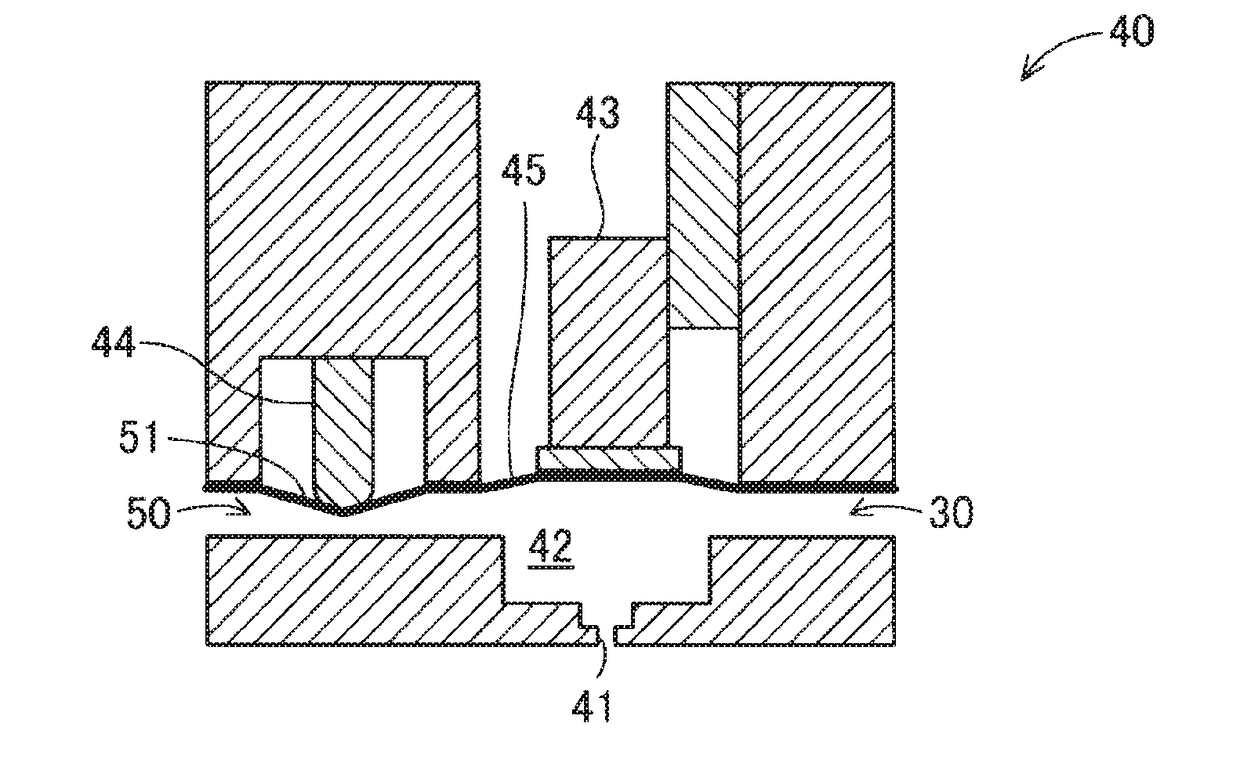
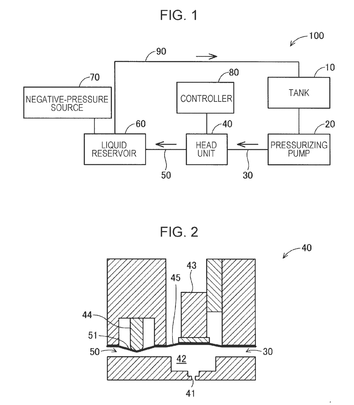
[0022]FIG. 1 is a view schematically illustrating the configuration of a liquid ejecting apparatus 100 of a first embodiment of the invention. The liquid ejecting apparatus 100 includes a tank 10, a pressurizing pump 20, an inflow passage 30, a head unit 40, an outflow passage 50, a liquid reservoir 60, a negative-pressure source 70, and a controller 80.

[0023]The tank 10 contains liquid. Examples of the liquid include ink having a prescribed viscosity. The liquid in the tank 10 is supplied to the head unit 40 through the inflow passage 30 by the pressurizing pump 20. The liquid supplied to the head unit 40 is ejected by the head unit 40. Operation of the head unit 40 is controlled by the controller 80.

[0024]A portion of the liquid which is not ejected by the head unit 40 is discharged into the liquid reservoir 60 through the outflow passage 50. The negative-pressure source 70 which may include various pumps is connected to the liquid reservoir 60. The negative-pressure source 70 ach...

second embodiment

[0042]FIG. 6 is a view schematically illustrating the configuration of a liquid ejecting apparatus 100A of a second embodiment of the invention. The liquid ejecting apparatus 100A of the present embodiment includes a head unit 40A including a plurality of liquid chambers 42, nozzles 41, and volume changing units 43. In the following description, a set of liquid chamber 42, nozzle 41, and volume changing unit 43 is referred to “head”. That is, in the present embodiment, the head unit 40A includes a plurality of heads.

[0043]The liquid chambers 42 of the heads are connected to respective branch inflow passages 301 branching from one inflow passage 30. Moreover, the liquid chambers 42 of the heads are connected to respective branch outflow passages 501 which join with each other to form one outflow passage 50 provided with one passage resistance changing unit 44. That is, in the present embodiment, one passage resistance changing unit 44 is commonly used by the plurality of heads. A con...

third embodiment

[0047]FIG. 8 is a view schematically illustrating the configuration of a head unit 40B of a third embodiment of the invention. In the third embodiment, the general configuration of the liquid ejecting apparatus 100 is the same as that of the first embodiment, and the configuration of a head unit 40B is different from that of the first embodiment.

[0048]Similarly to the first embodiment, the head unit 40B in the present embodiment includes a nozzle 41, a liquid chamber 42, and a passage resistance changing unit 44. In the present embodiment, the head unit 40B further includes a first volume changing unit 431 and a second volume changing unit 432 as volume changing units. The configuration of the first volume changing unit 431 is the same as that of the volume changing unit 43 of the first embodiment. The second volume changing unit 432 is disposed between the first volume changing unit 431 and the passage resistance changing unit 44 and includes a piezo actuator configured to displace...


PUM


Abstract

A liquid ejecting apparatus includes a liquid chamber in communication with a nozzle, a volume changing unit configured to change a volume of the liquid chamber, an inflow passage through which the liquid flows into the liquid chamber, an outflow passage through which the liquid flows out of the liquid chamber, a passage resistance changing unit configured to change a passage resistance of the outflow passage, and a controller configured to control the volume changing unit to reduce the volume of the liquid chamber so as to cause the liquid to be ejected through the nozzle. In filling the liquid chamber with the liquid for ejection of the liquid through the nozzle, the controller controls the passage resistance changing unit to change the passage resistance of the outflow passage to an increased passage resistance and controls the volume changing unit to increase the volume of the liquid chamber.

Description

BACKGROUND1. Technical Field[0001]The present invention relates to a liquid ejecting apparatus and a liquid ejection method.2. Related Art[0002]For example, JP-A-2011-213094 describes a circulating ink jet apparatus. In the circulating ink jet apparatus, a passage resistance of an ink outlet channel in communication with an ink chamber is increased in ejecting ink so that driving force of an actuator for ejection of the ink in the ink chamber is suppressed from escaping into the ink outlet channel.[0003]However, according to the technique described in JP-A-2011-213094, when the passage resistance of the ink outlet channel is increased, the ink may flow back from the ink outlet channel to the ink chamber as the volume of the ink outlet channel decreases, which may lead to leakage of the ink through a nozzle in communication with the ink chamber. Thus, there is a demand for a technique for enabling a reduction in leakage of unnecessary ink through a nozzle. Such a problem is found not...

Claims


Application Information

Patent Timeline
IPC IPC(8): B41J2/14B41J2/16B41J2/175
CPCB41J2/14274B41J2/1626B41J2/17593B41J2/14072B41J2202/12B41J2002/14306B41J2/045B41J2/18B41J2202/05
Inventor KATAKURA, TAKAHIROSUGAI, KEIGOSAKAI, HIROFUMINAKAMURA, SHINICHISANO, JUNICHI
Owner SEIKO EPSON CORP
Why Eureka
Try Eureka