
Virtual Radar Apparatus and Method

a radar and virtual technology, applied in the field of virtual radar apparatus and methods, can solve the problems of high system cost, the proximity of other vehicles, persons, objects, and aircraft to each other, and the danger of airports or seaports, respectively

Inactive Publication Date: 2018-10-04
AIRPROX USA INC
View PDF6 Cites 29 Cited by
  • Summary
  • Abstract
  • Description
  • Claims
  • Application Information

AI Technical Summary

Benefits of technology

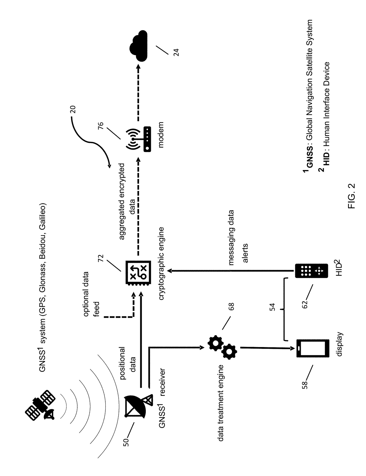
The invention is a virtual radar system that includes a vehicle-based subsystem and a cloud-based data subsystem. The vehicle-based subsystem includes a GNSS receiver, a vehicle subsystem processor, a human interface subsystem, and a network modem. The cloud-based data subsystem includes a database for holding data about vehicles, cloud transaction processors, and a network modem. The system calculates the positions of vehicles, their trajectories, and the probability of collisions between them, and issues a warning to the vehicles in response. The virtual radar system can be used in vehicles and as a mobile device subsystem. The system can also include a control station subsystem and a control station network modem. The technical effects of the invention include improved safety and efficiency for vehicles and better data management for the cloud-based data subsystem.

Problems solved by technology

However, once on the ground, the crowded conditions caused by the various aircraft, landing, taking off, taxiing, or parked, in conjunction with the numerous other types of vehicles, such as fuel trucks, cars, cargo carriers, and tugs in conjunction with stationary objects such as buildings, paved and unpaved ways, and other structures, such as radio masts, portable shelters and construction materials, make the airport or seaport an equally dangerous place for both the aircraft, or seacraft, respectively, and the other vehicles, persons, and objects moving in close proximity to one another.
However, these systems are expensive, are somewhat hampered by objects in the way of the scanning radar beam, and may not have the resolution to detect something as small as a tug with enough resolution to detect collision trajectories.

Method used


Image

  • Virtual Radar Apparatus and Method
  • Virtual Radar Apparatus and Method
  • Virtual Radar Apparatus and Method

Examples


Embodiment Construction

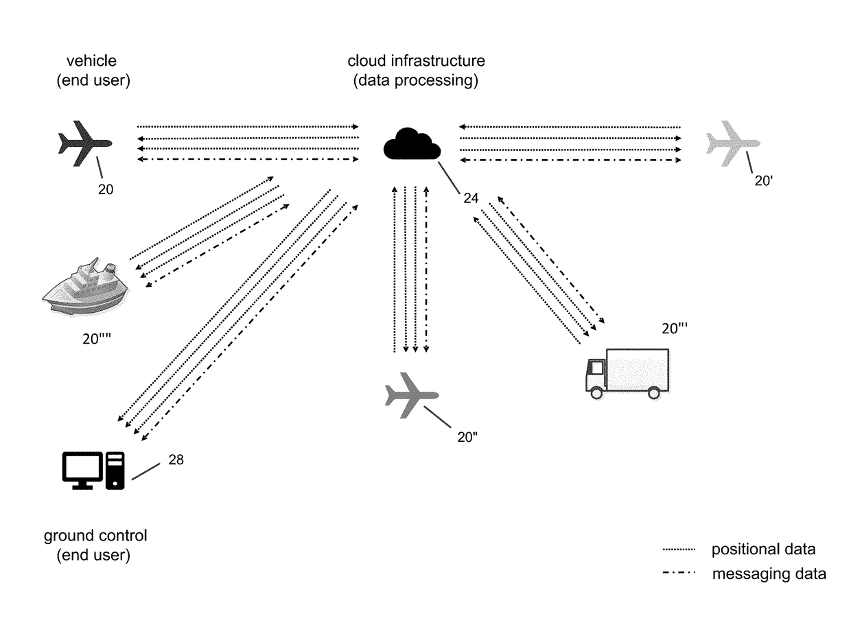
[0036]Referring to FIG. 1, a general mode of operation of the system of the invention is shown. Each mobile user vehicle 20, 20′, 20″, 20′″, 20″″ (generally 20), which may include aircraft, ground vehicles, water vehicles, other movable objects and even individuals uses a vehicle-based mobile unit (described below) that sends position updates to the system's servers 24 at a given update frequency which depends on the vehicle type and its potential speed. For simplicity, the application refers to vehicle-based mobile units or vehicle-based device interchangeably and without regard to what object actually includes the device. For example, an aircraft in the air may have its position updated 4 times per second, while an aircraft on the ground may update once every second and a boat's position may be updated 10 times per minute. In one embodiment, the servers are in the internet cloud but in other embodiments, the servers may be located locally. The servers 24 periodically send the posi...


PUM


Abstract

A virtual radar system. In one embodiment, the system includes a vehicle-based mobile device subsystem, said vehicle-based mobile device subsystem located in a vehicle; a control station subsystem, and a cloud-based data subsystem comprising a cloud-based database for holding data regarding a plurality of locations of a plurality of vehicles and a plurality of cloud transaction processors in communication with the cloud-based database. In another embodiment, said cloud transaction processors calculate the positions of the plurality of vehicles, their trajectories, and the probability of a collision between vehicles and issue a warning to the vehicles in response thereto.

Description

RELATED APPLICATIONS[0001]This application claims priority to U.S. Provisional Patent Application No. 62 / 479,435 filed on Mar. 31, 2017, the contents of which is incorporated herein by reference in its entirety.FIELD OF THE INVENTION[0002]The invention relates generally to a system and method for locating objects in the vicinity of a vehicle without the need for on-board proximity detection systems and, more specifically, for locating the position of objects in the vicinity of a vehicle using a server-based database.BACKGROUND OF THE INVENTION[0003]The invention provides any vehicle, or for that matter any object, with an elegant yet simple solution to help enhance safety by constructing a virtual radar system to be used by both a vehicle operator and by a traffic control operator or other operators or controllers. The vehicles may be aircraft, land craft or watercraft and the traffic control operators may be air traffic control, land traffic control, or harbor control operators. By...

Claims


Application Information

Patent Timeline
Patent Type & Authority Applications(United States)
IPC IPC(8): G08G9/02G01S19/15G01S19/37
CPCG08G9/02G01S19/15G01S19/37B64D45/00B64D2045/0065B63B45/00B60Y2400/3017G08G1/164G08G1/166G08G3/02G08G5/0013G08G5/0021G08G5/0026G08G5/0082G08G5/045G08G5/065
Inventor DERBANNE, MATHIEU A.
Owner AIRPROX USA INC
Learn More