OLED panel and image display device including the same

a display device and image technology, applied in the field of image display devices, can solve the problems that the conventional use of oled display devices for touch sensors may be easily broken or fractured, and achieve the effect of improving the visible property

Active Publication Date: 2018-10-04
DONGWOO FINE CHEM CO LTD
View PDF0 Cites 28 Cited by
  • Summary
  • Abstract
  • Description
  • Claims
  • Application Information

AI Technical Summary

Benefits of technology

[0091]The optical layer 40 may include, e.g., a polarizing plate. Preferably, the polarizing plate having a thickness of about 10 μm to about 150 μm and an elastic modulus of about 1,000 MPa to about 4,000 MPa. The polarizing plate may include a polarizer and a protective film formed on at least one surface of the polarizer.
[0092]The polarizer commonly used in the related art may be used. For example, the polarizer may include a stretching type polarizer prepared by swelling, dyeing, cross-linking, stretching, washing and drying a polarizer forming film, a coating type polarizer prepared by curing a liquid crystal composition, or a combination thereof.
[0093]When the touch sensor layer 30 is included in the OLED module layer 10, the polarizing plate including the stretching type polarizer may be preferably used. When the touch sensor layer 30 is included in the stack structure formed on the surface of the first adhesive layer 20 which may not be in contact with OLED module layer 10, the polarizing plate including the coating type polarizer may be used.
[0094]The polarizer forming film may include, e.g., a dichroic material that may be dyed by iodine. For example, the polarizer forming film may include a polyvinyl alcohol film, a dehydrated polyvinyl alcohol film, a dehydrochlorinated polyvinyl alcohol film, a polyethylene terephthalate film, an ethylene-acetic acid vinyl copolymer film, an ethylene-vinyl alcohol copolymer film, a cellulose film or a partially saponificated film thereof. Among these films, the polyvinyl alcohol film may be preferably used from the aspects of obtaining uniformity of in-plane polarizing degree and iodine dyeing affinity.
[0095]The protective film may include a film having improved transparency, mechanical strength, moisture blocking property, isotropic property, etc. For example, a polyester-based film such as polyethylene terephthalate, polyethylene isophthalate, polybutylene terephthalate, etc.; a cellulose-based film such as diacetyl cellulose, triacetyl cellulose, etc.; a polycarbonate-based film; an acryl-based film such as polymethyl(meth)acrylate, polyethyl(meth)acrylate, etc.; a styrene-based film such as polystyrene, an acrylonitrile-styrene copolymer; a polyolein-based film such as cycloolefin, a cycloolefin copolymer, polynorbornene, polypropylene, polyethylene, an ethylene-propylene copolymer; a polyvinyl chloride-based film; a polyamide-based film such as nylon, an aromatic polyamide; an imide-based film; a sulfone-based film; a polyether ketone-based film; a polyphenylene sulfide-based film; a vinylalcohol-based film; a vinylidene chloride-based film; a vinyl butyral-based film; an allylate-based film; a polyoxy methylene-based film; an urethane-based film; an epoxy-based film; a silicone-based film, etc. Among these films, the cellulose-based film having a saponificated surface with an alkali may be preferably used in consideration of polarizing property and durability. The protective film may also have an optical compensation property such as a retardation property.
[0096]In an embodiment, the touch sensor layer 30 may be directly formed on the optical layer 40. For example, at least one member of the touch sensor layer 30 may be disposed on at least one surface of the protective film. The one member of the touch sensor layer 30 may be at least one of the sensing electrodes. In this case, the OLED panel may become thinner and have an enhanced visible property.

Problems solved by technology

However, an OLED panel and a touch sensor conventionally used in an OLED display device may be easily broken or fractured when a bending force is applied.

Method used


Image

  • OLED panel and image display device including the same
  • OLED panel and image display device including the same
  • OLED panel and image display device including the same

Examples


example 1

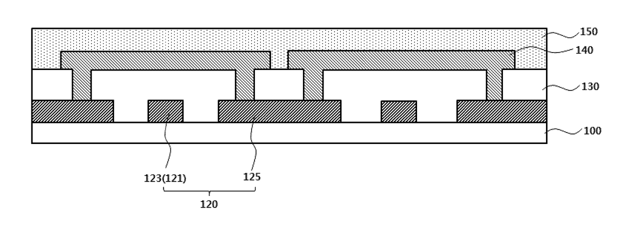
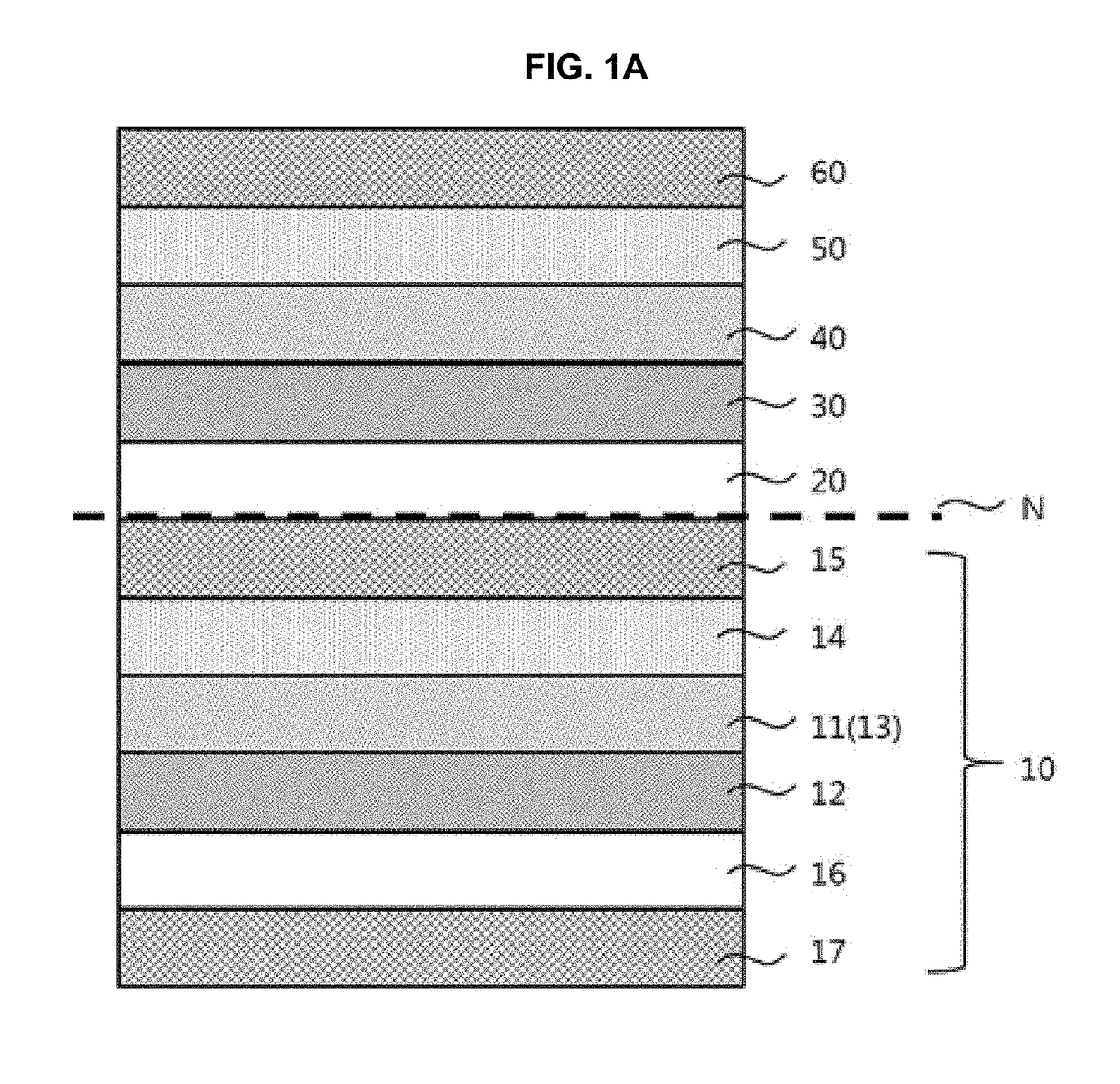
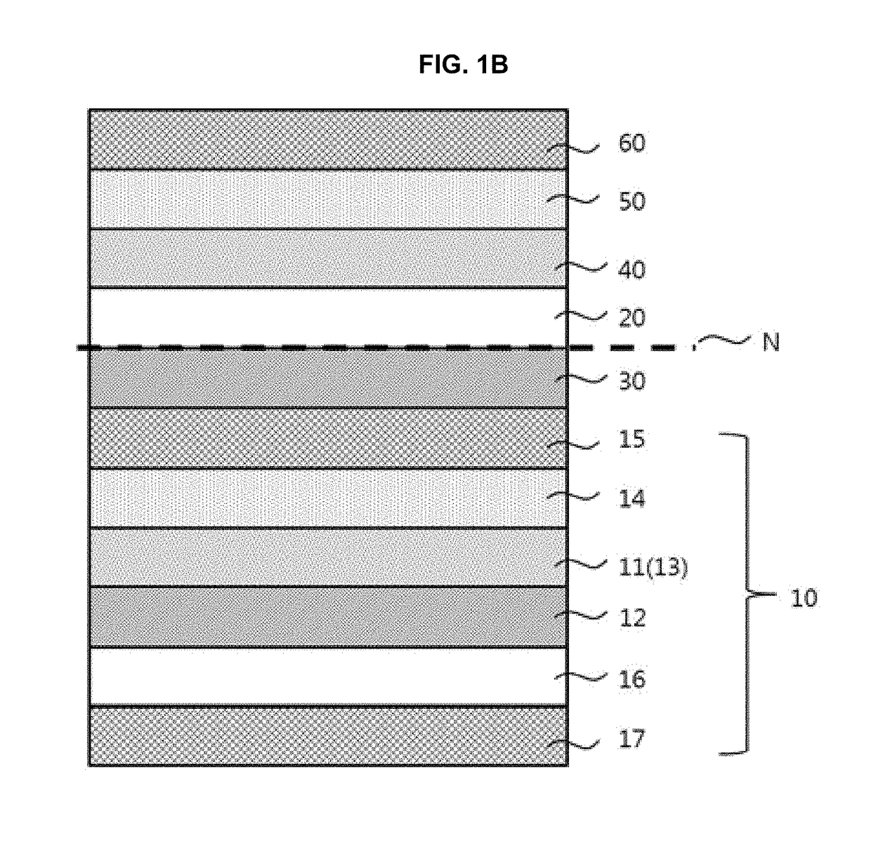
[0103]An anode, an organic layer including an organic light emitting layer, a cathode and an encapsulation layer were sequentially formed on a polyimide-based substrate (10 cm×10 cm, thickness: 30 μm), and then an acryl-based polymer was coated thereon to form a first adhesive layer.

[0104]Next, a touch sensor layer, a polarizing plate including a stretching type polarizer as an optical layer, an acryl-based adhesive layer and a polyimide-based window substrate were further stacked. In the touch sensor layer, an ITO electrode layer was formed on a triacetyl cellulose film. In the polarizing plate, triacetyl cellulose protective films were formed on both sides of a polyvinyl alcohol polarizer film and an optical compensation film was formed on one surface of the protective film.

[0105]A thickness of an OLED module layer was 180 μm, and an elastic modulus of the OLED module layer was 4,000 MPa. A thickness and an elastic modulus of the first adhesive layer were 50 μm and 0.1 MPa, respec...

example 2

[0106]Processes the same as those of Example 1 were performed except that a thickness and an elastic modulus of the OLED module layer were 250 μm and 1,600 MPa, respectively.

example 3

[0107]Processes the same as those of Example 1 were performed except that a thickness and an elastic modulus of the first adhesive layer were 200 μm and 0.3 MPa, respectively.


PUM


Abstract

An organic light emitting diode (OLED) panel includes an OLED module layer, and a first adhesive layer formed on a surface of the OLED module layer. A neutral plane is formed at an interface between the first adhesive layer and the OLED module layer. A bending deformation and a stress of the OLED module layer may be avoided, and damages of the OLED module layer may be reduced.

Description

CROSS-REFERENCE TO RELATED APPLICATION AND CLAIM OF PRIORITY[0001]This application claims priority to Korean Patent Application No. 10-2017-0040917 filed on Mar. 30, 2017 in the Korean Intellectual Property Office (KIPO), the entire disclosure of which is incorporated by reference herein.BACKGROUND1. Field[0002]The present invention relates to an OLED panel and an image display device including the same.2. Description of the Related Art[0003]As information technologies are being developed, various demands in display devices having thinner dimension, light-weight, high efficiency in power consumption, etc., are increasing. The display device may include a flat panel display device such as a liquid crystal display (LCD) device, a plasma display panel (PDP) device, an electro-luminescent display device, an organic light emitting diode (OLED) display device, etc.[0004]Among the display devices, the OLED display device is highlighted recently because of high response speed, high image qu...

Claims


Application Information

Patent Timeline
Patent Type & Authority Applications(United States)
IPC IPC(8): H01L51/52H01L27/32H01L23/552G06F3/041
CPCH01L51/5253H01L51/5246H01L27/323H01L23/552H01L51/5281G06F3/041H01L2251/558H01L2251/5338G06F2203/04102H10K59/40H10K50/84G06F3/0412G06F3/046G06F2203/04106G06F2203/04107Y02E10/549G06F3/0446G06F3/0443G06F2203/04111H10K77/111H10K50/844H10K2102/311H10K2102/351H10K50/85H10K50/86H10K50/8426
Inventor SONG, IN KYUSUNG, JUN HEE
Owner DONGWOO FINE CHEM CO LTD
Why Eureka
Try Eureka