Wireless charging device alignment guiding method and device and system for same

a wireless charging and alignment guide technology, applied in the direction of transformers, inductances, transportation and packaging, etc., can solve the problems of reducing consuming a lot of energy, so as to maximize the efficiency of wireless charging and minimize power waste.

Inactive Publication Date: 2018-10-04
SCRAMOGE TECH LTD
View PDF0 Cites 18 Cited by
  • Summary
  • Abstract
  • Description
  • Claims
  • Application Information

AI Technical Summary

Benefits of technology

[0040]Accordingly, the present invention provides the following effects or advantages.
[0041]According to the present invention, it is able to provide a method of guiding alignment of a wireless charging device and an apparatus and system therefor.
[0042]According to the present invention, it is able to provide a method of guiding alignment of a wireless charging device capable of guiding an optimal position of the wireless charging device via a screen and an apparatus and system therefor.
[0043]According to the present invention, it is able to minimize power waste by maximizing wireless charging

Problems solved by technology

An issue of supplying power provided to the devices and the sensors is becoming a new challenge.
As a type of a portable device such as a smartphone, a Bluetooth handset, a music player (e.g., iPod), and the like is rapidly increasing, recharging a battery requires time and effort for a user.
However, since maximum transmission length is equal to or less than 1 cm, the electromagnetic induction method has a demerit in that it is necessary to place a device near a charger or a floor in general.
On the other hand, the electromagnetic resonance method has a demerit in that the method is used in a confined distance and space only and has a little bit lower energy transfer efficiency.
In general, since a transmitting coil configured to trans

Method used


Image

  • Wireless charging device alignment guiding method and device and system for same
  • Wireless charging device alignment guiding method and device and system for same
  • Wireless charging device alignment guiding method and device and system for same

Examples


Embodiment Construction

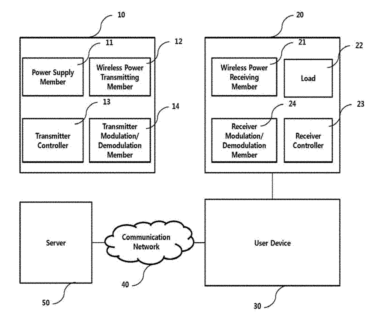
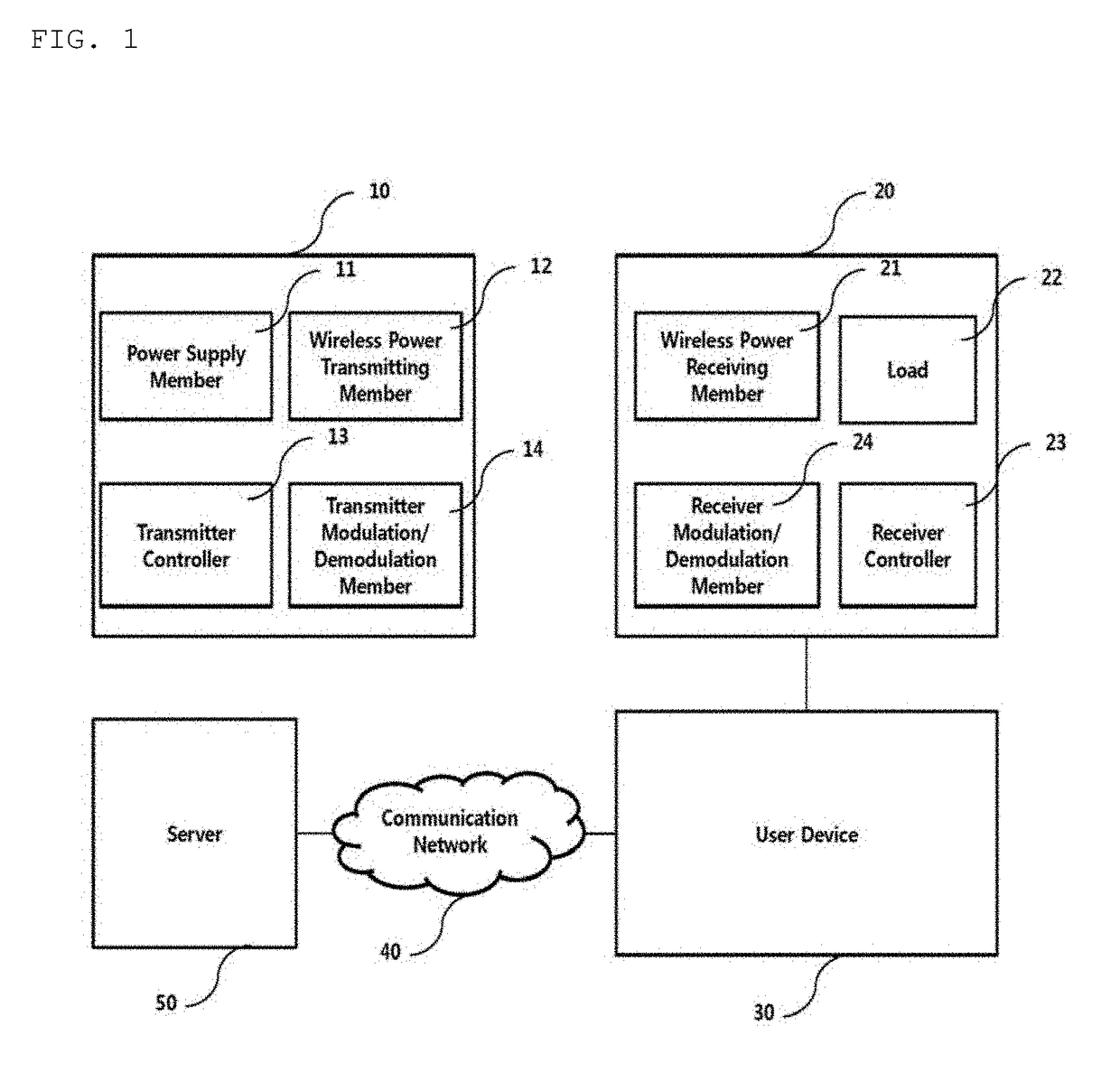
[0059]In the following, a device to which embodiments of the present invention are applied and various methods are explained in more detail with reference to the accompanying drawings. In general, a suffix such as “module” and “member” may be used to refer to elements or components. Use of such a suffix herein is merely intended to facilitate description of the specification, and the suffix itself is not intended to give any special meaning or function.

[0060]In the above, although it is explained as all configuration elements constructing embodiments of the present invention are combined by one or operate in a manner of being combined, the present invention is not restricted to the embodiments. In particular, all configuration elements may operate in a manner of being selectively combined using one or more configuration elements within the scope of the present invention. Although it is able to implement each of the configuration elements as independent hardware, all or a part of the...


PUM


Abstract

The present invention relates to a wireless charging device alignment guiding method and a device and system for same. A wireless charging device that receives power through a receiving coil from a wireless power transmitter provided with a transmitting coil, when the reception of power through the receiving coil is detected, may comprises: a power sensor for measuring the intensity of received power; a coil arranged state determining member for determining the current arranged states of the transmitting coil and the receiving coil on the basis of the measured power intensity; a device control member for generating a coil arrangement screen corresponding to the determined current arranged state; and a display member for outputting the generated coil arrangement screen. Accordingly, the present invention has the advantage of being able to effectively guide the position of a wireless charging device to where charging efficiency is optimal.

Description

TECHNICAL FIELD[0001]The present invention relates to wireless charging, and more particularly, to a method of guiding alignment of a wireless charging device capable of guiding a charging area position having optimal wireless charging efficiency to be intuitively recognized and an apparatus and system therefor.BACKGROUND ART[0002]Recently, in accordance with the rapid development of information and communication technologies, ubiquitous society is realized based on the information and communication technologies.[0003]In order to access IT devices at anytime and anywhere, it is necessary to install sensors in which a computer chip equipped with a communication function is embedded in all social facilities. An issue of supplying power provided to the devices and the sensors is becoming a new challenge. As a type of a portable device such as a smartphone, a Bluetooth handset, a music player (e.g., iPod), and the like is rapidly increasing, recharging a battery requires time and effort...

Claims


Application Information

Patent Timeline
IPC IPC(8): H02J7/02H02J5/00H02J50/90H02J50/40H01F38/14
CPCH02J7/025H02J5/005H02J50/90H02J50/40H01F38/14H04M2201/38H02J50/402H02J7/00H02J7/02
Inventor JUNG, WOO KIL
Owner SCRAMOGE TECH LTD
Why Eureka
Try Eureka