Physiological monitoring device

a monitoring device and physiological technology, applied in the field of medical devices, can solve the problems of difficult rapid and reliable diagnosis, cumbersome wires, and daily change of electrodes, and achieve the effects of preventing mechanical stress on the printed circuit board, minimizing signal distortion, and convenient location

Active Publication Date: 2018-10-11
IRHYTHM TECH
View PDF0 Cites 26 Cited by
  • Summary
  • Abstract
  • Description
  • Claims
  • Application Information

AI Technical Summary

Benefits of technology

[0012]Embodiments described herein are directed to a physiological monitoring device that may be worn continuously and comfortably by a human or animal subject for at least one week or more and more typically two to three weeks or more. In one embodiment, the device is specifically designed to sense and record cardiac rhythm (i.e., electrocardiogram, ECG) data, although in various alternative embodiments one or more additional physiological parameters may be sensed and recorded. The physiological monitoring device includes a number of features to facilitate and / or enhance the patient experience, to make diagnosis of cardiac arrhythmias more accurate, and to make manufacture of the device more simple and cost effective.
[0015]a printed circuit board assembly housed within the rigid housing, wherein the rigid housing is configured to prevent deformation of the printed circuit board in response to movement of the mammal;
[0020]In embodiments, the motion signals can be collected in time with the physiological signals. In certain embodiments, a motion artifact is identified when the physiological signals and the motion signals match. Further embodiments may call for an event trigger coupled to the printed circuit board assembly. In some embodiments, the event trigger input is supported by the rigid housing so as to prevent mechanical stress on the printed circuit board when the trigger is activated. The event trigger may be concave and larger than a human finger such that the event trigger is easily located. In certain embodiments, the electrode traces are configured to minimize signal distortion during movement of the mammal. In particular embodiments, gaskets may be used as a means for sealable attachment to the rigid housing.

Problems solved by technology

Since the symptoms listed above can often be due to other, less serious causes, a key challenge is to determine when any of these symptoms are due to an arrhythmia.
Oftentimes, arrhythmias occur infrequently and / or episodically, making rapid and reliable diagnosis difficult.
The electrodes need daily changing and the wires are cumbersome.
The devices also have limited memory and recording time.
Wearing the device interferes with patient movement and often precludes performing certain activities while being monitored, such as bathing.
All of these limitations severely hinder the diagnostic usefulness of the device, the compliance of patients using the device and the likelihood of capturing all important information.
Lack of compliance and the shortcomings of the devices often lead to the need for additional devices, follow-on monitoring or other tests to make a correct diagnosis.
Current methods to correlate symptoms with the occurrence of arrhythmias, including the use of cardiac rhythm monitoring devices, such as Holter monitors and cardiac event recorders, are often not sufficient to allow an accurate diagnosis to be made.
Additionally, the medical treatment process to actually obtain a cardiac rhythm monitoring device and initiate monitoring is typically very complicated.
This appointment is usually several weeks from the initial visit with the PCP, which in itself leads to a delay in making a potential diagnosis as well as increases the likelihood that an arrhythmia episode will occur and go undiagnosed.
Once the monitoring has been completed, the patient typically must return the device to the clinic, which itself can be an inconvenience.
This complex process results in fewer patients receiving cardiac rhythm monitoring than would ideally receive it.
However, since the trigger is part of a skin-contacting platform with integrated electrodes, the patient can introduce significant motion artifacts when feeling for the trigger.
Secondly, patient compliance and device adhesion performance are two factors that govern the duration of the ECG record and consequently the diagnostic yield.

Method used


Image

  • Physiological monitoring device
  • Physiological monitoring device
  • Physiological monitoring device

Examples


Embodiment Construction

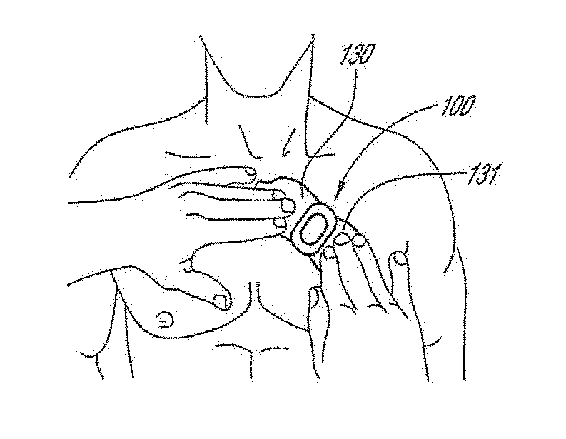
[0045]The following description is directed to a number of various embodiments. The described embodiments, however, may be implemented and / or varied in many different ways without departing from the scope of the invention. For example, the described embodiments may be implemented in any suitable device, apparatus, or system to monitor any of a number of physiological parameters. For example, the following discussion focuses primarily on long-term, patch-based cardiac rhythm monitoring devices. In one alternative embodiment, a physiological monitoring device may be used, for example, for pulse oximetry and diagnosis of obstructive sleep apnea. In various alternative embodiments, one size of physiological monitor may be used for adult patients and another size may be used for pediatric patients. The method of using a physiological monitoring device may also vary. In some cases, a device may be worn for one week or less, while in other cases, a device may be worn for at least seven day...


PUM


Abstract

The present invention relates to a physiological monitoring device. Some embodiments of the invention allow for long-term monitoring of physiological signals. Further embodiments may also allow for the monitoring of secondary signals such as motion.

Description

CROSS-REFERENCE TO RELATED APPLICATIONS[0001]This application is a continuation of U.S. patent application Ser. No. 14 / 162,656, filed, Jan. 23, 2014, which claims the benefit of U.S. Provisional Application No. 61 / 756,326, filed Jan. 24, 2013, entitled PHYSIOLOGICAL MONITORING DEVICE. The contents of the aforementioned applications are hereby incorporated by reference in their entireties as if fully set forth herein. The benefit of priority to the foregoing application is claimed under the appropriate legal basis, including, without limitation, under 35 U.S.C. § 119(e).BACKGROUNDField of the Invention[0002]The invention relates generally to medical devices. More specifically, the invention relates to a physiological monitoring device and method for use.Description of the Related Art[0003]Abnormal heart rhythms, or arrhythmias, may cause various types of symptoms, such as loss of-consciousness, palpitations, dizziness, or even death. An arrhythmia that causes such symptoms is often a...

Claims


Application Information

Patent Timeline
Patent Type & Authority Applications(United States)
IPC IPC(8): A61B5/0408A61B5/00A61B5/296A61B5/332
CPCA61B5/6833A61B5/0408A61B5/721A61B2562/125A61B2562/0219A61B2562/164A61B5/25A61B5/257A61B5/265A61B5/266A61B5/263A61B2562/0209A61B2562/0215A61B2562/16
Inventor BAHNEY, TIMOTHY J.HO, HUNG H.PARK, SHENA H.SEPULVEDA, GENARO S.DAY, MARK J.TAMURA, YURIKO
Owner IRHYTHM TECH
Why Eureka
Try Eureka