Nozzle cleaner device

Inactive Publication Date: 2018-10-11
SHINKOKIKI CO LTD
View PDF4 Cites 2 Cited by
  • Summary
  • Abstract
  • Description
  • Claims
  • Application Information

AI Technical Summary

Benefits of technology

The nozzle cleaner device can be easily attached to a robot arm and the main body of the device has a polishing part that can remove spatter from the nozzle. The polishing part can rotate around the nozzle to remove spatter from the inner surface. Additionally, a cutting part can be formed on the polishing part to efficiently cut and remove spatter. The device is designed to easily and safely remove spatter without disassembling the electrode. Overall, the nozzle cleaner device simplifies the process of removing spatter and ensures the continued functionality of the electrode.

Problems solved by technology

When this arc welding is continuously performed, attachments such as welding waste and dust, called spatter, are deposited within the nozzle, and this spatter is likely to prevent accurate welding process.
However, a method including detaching the nozzle, for example, from a robot arm, thereafter further disassembling the nozzle and the contact tip and manually brushing the nozzle is commonly used to clean the nozzle, and involves the problem of being troublesome and requiring a long time.
When spatter is blown off with compressed air, complete removal thereof is difficult, and the spatter disadvantageously contaminates an environment.
Further, no troublesome cleaning process would be necessary if the nozzle is replaced with a new one, but there are caused the problems that the cost is increased, and, additionally, that the quantity of garbage to be discarded is also increased, leading to wasteful consumption of resources.
However, the device descried in Patent Literature 1 is a device which uses a dedicated cutter to shave spatter off, has a complex structure, and disadvantageously requires periodical replacement of the cutter and therefore troublesome maintenance.
The device described in Patent Literature 2, which has previously been proposed by the present applicant, is a device which uses a coil spring to shave spatter off, and disadvantageously causes shaving unevenness in some cases and requires a complicated coil spring replacement operation.

Method used


Image

  • Nozzle cleaner device
  • Nozzle cleaner device
  • Nozzle cleaner device

Examples


Embodiment Construction

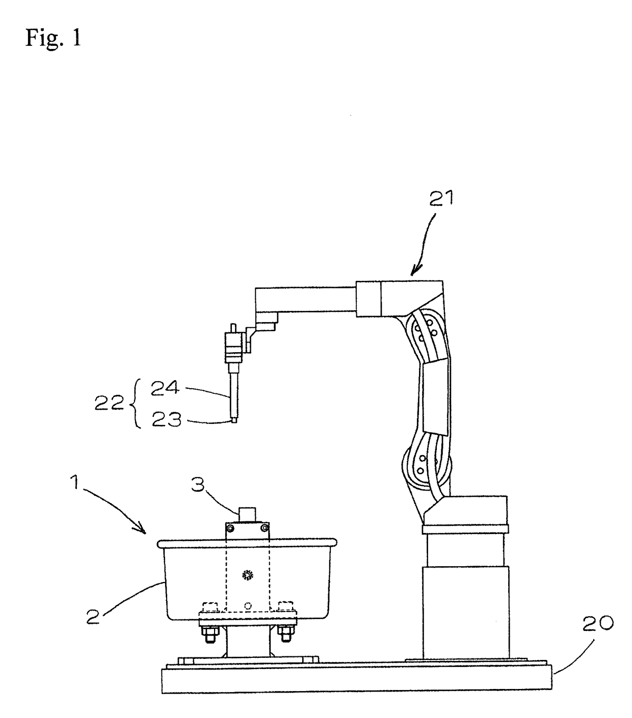
[0027]Hereinafter, preferred embodiments of the present invention will be illustrated with reference to the drawings.[0028]FIG. 1 is a front view of a nozzle cleaner device according to the present invention. In this figure, reference sign 20 indicates a base stand; 21 indicates a robot arm for welding; and 22 indicates an electrode for arc welding, which is mounted at a tip end of the robot arm 21. This electrode 22 is composed of a contact tip 23 and a cylindrical nozzle 24 surrounding the contact tip 23. The robot arm 21 is configured so as to be freely bent and rotated to move the electrode 22 at the tip end to a predetermined position and to thereby conduct a welding process of a work which is a substance to be welded (not shown).

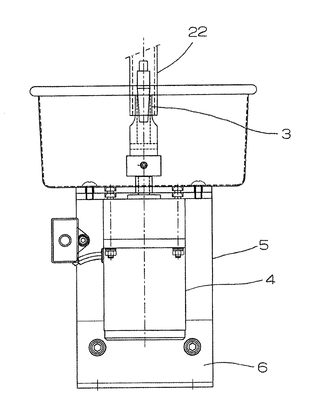
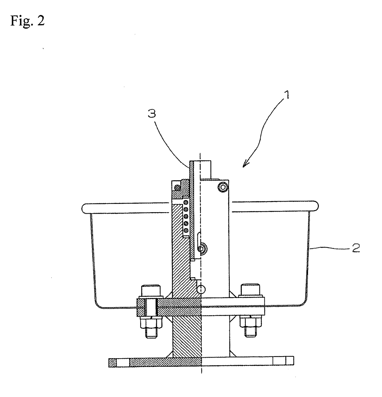
[0029]In the operation area of the robot arm 21, a main body 1 of the cleaner device is provided separately from the work station for conducting welding, and has a structure capable of freely carrying the nozzle 24 mounted at a tip end of the robot arm...


PUM


Abstract

A nozzle cleaner device attached to a tip end of a nozzle used in arc welding is provided. The nozzle cleaner device is for removing spatter attached to a tip end of a nozzle of an electrode for arc welding, including a main body provided within an operation area of a robot arm which operates the electrode, the main body of the cleaner device includes a tub-shaped box body and a polishing part erected at a center part of the bottom surface of the box body; the polishing part is made of a material softer than a metal which constitutes the nozzle, and formed in a cylinder shape that can be inserted into the nozzle; and the nozzle onto which spatter is attached is carried to the main body of the cleaner device to remove the spatter by means of the polishing part inserted into the nozzle.

Description

TECHNICAL FIELD[0001]The present invention relates to a nozzle cleaner device which can easily remove spatter attached to a tip end of a nozzle used in arc welding.BACKGROUND ART[0002]Conventionally, arc welding has widely been utilized as a means for spot-coupling various parts such as automobile parts. As electrodes used in this arc welding, those in which a cylindrical nozzle covers the periphery of a contact tip mounted at a tip end of a tip holder are commonly used. When this arc welding is continuously performed, attachments such as welding waste and dust, called spatter, are deposited within the nozzle, and this spatter is likely to prevent accurate welding process. So, it is necessary to periodically detach and clean the nozzle, to periodically spray compressed air onto the nozzle to blow the spatter off, or to replace the nozzle with a new one.[0003]However, a method including detaching the nozzle, for example, from a robot arm, thereafter further disassembling the nozzle a...

Claims


Application Information

Patent Timeline
IPC IPC(8): B08B9/02B08B9/04B23K9/32
CPCB08B9/021B08B9/04B23K9/328B08B1/005B05B15/5223B08B1/165
Inventor FUKIZAWA, TAKEOMASUOKA, ETSUOISHII, HIDEHIRO
Owner SHINKOKIKI CO LTD
Why Eureka
Try Eureka