Eureka AIR delivers breakthrough ideas for toughest innovation challenges, trusted by R&D personnel around the world.

Position marking and reference method and system for the practice

Inactive Publication Date: 2013-04-04
SMID G EDZKO
View PDF9 Cites 2 Cited by
  • Summary
  • Abstract
  • Description
  • Claims
  • Application Information

AI Technical Summary

Benefits of technology

The patent describes a way to accurately position and track objects in space without needing to move them. This is done by using reference beacons and a calibration process to make sure the object's reference frame is aligned with the beacons. This method makes it easier to measure the object's position and reduces the chance of human error. The system also provides more user-friendly positioning information for the operator.

Problems solved by technology

GPS has several draw backs including relatively weak signals that do not penetrate heavy ground cover and / or man-made structures.
Furthermore, the weak signals require a sensitive receiver.
GPS also utilizes a single or narrow band of frequencies that are relatively easy to block or otherwise jam, and can easily reflect off surfaces, resulting in multi-path errors.
The accuracy of the GPS system relies heavily on the use of atomic clocks, which are expensive to make and operate.
A problem arises in that a local coordinate reference system based on reference beacons is typically not correlated to the object's reference frame; and as a result, the object must positioned accurately at a specific reference location and at a specific orientation within the local coordinate reference frame before position tracking on the object can take place.
Positioning the object in proper location and orientation may be challenging if the object is large, heavy, fragile, immobile or a combination thereof.

Method used


Image

  • Position marking and reference method and system for the practice
  • Position marking and reference method and system for the practice

Examples


Embodiment Construction

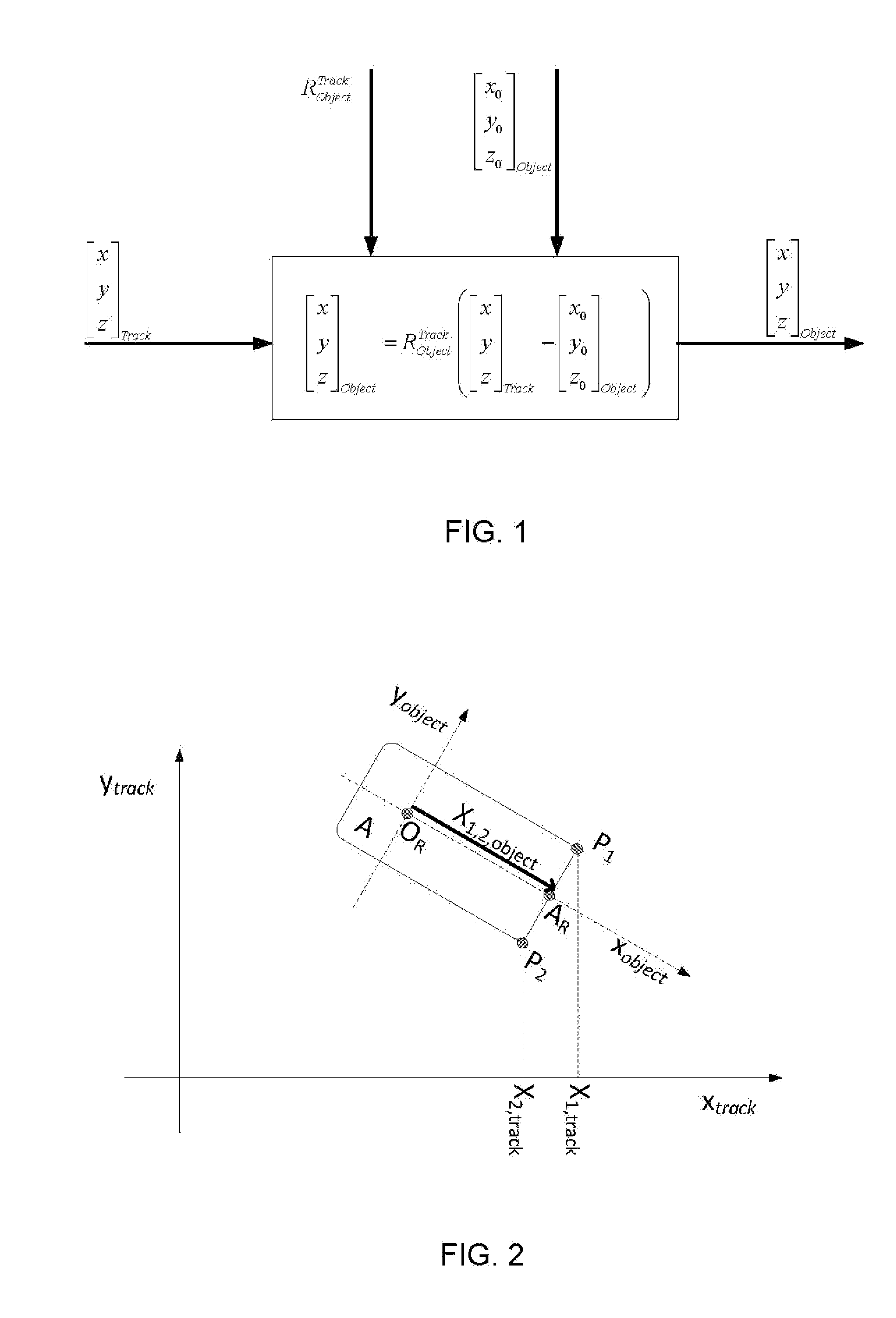
[0013]The present invention has utility in position marking and referencing to register precise locations on free stationary objects in space, and to refer back to that same precise location at a later time, while establishing a local coordinate system without consideration for the object's global location or orientation, thereby ensuring the object does not need to be re-positioned or re-orientated before marking and referring to any object's locations. The present invention has applications in fields as varied as quality control, forensics, civil engineering structural monitoring, geology, surgery, dentistry, and archaeology. Additional benefits provided by embodiments of the invention include commercial benefits such as labor savings, by eliminating consideration for coordinate setup and physically moving the object in the operating space, a more robust measurement, since eliminating considerations for setup, and replacing them with an easy to conduct calibration process reduces ...


PUM


Abstract

A method and system are provided for position marking to register precise locations on a stationary objects in space, and to refer back to the locations that same precise location at a later time, while establishing a local coordinate system without consideration for the global location or orientation of the object, thereby ensuring the object does not need to be re-positioned or re-orientated before marking and referring to any object's locations. The problem that a local coordinate reference system based on reference beacons is not correlated to the object's reference frame is addressed through a novel calibration method. By eliminating consideration for coordinate setup and the need to physically move the object in the operating space, a more robust measurement is achieved that replaces such conventional steps with an easy to conduct calibration process that reduces the chance for human error.

Description

CROSS-REFERENCE TO RELATED APPLICATIONS[0001]This application is a non-provisional application that claims priority benefit of U.S. Provisional Application Ser. No. 61 / 541,486, filed Sep. 30, 2011 the contents of which are hereby incorporated by reference.FIELD OF THE INVENTION[0002]The present invention in general relates to position measurement, and in particular to a method for providing position location measurements of objects.BACKGROUND OF THE INVENTION[0003]The Global Positioning System (GPS) is based on the fixed location base stations and the measurement of time-of-flight of accurately synchronized station signature transmissions. The base stations for the GPS are satellites and require atomic clocks for synchronization.[0004]GPS has several draw backs including relatively weak signals that do not penetrate heavy ground cover and / or man-made structures. Furthermore, the weak signals require a sensitive receiver. GPS also utilizes a single or narrow band of frequencies that ...

Claims


Application Information

Patent Timeline
IPC IPC(8): G01S3/02
CPCG01S5/0284G01S19/51
Inventor SMID, G. EDZKO
Owner SMID G EDZKO
Why Eureka
Eureka Blog
Learn More