
Laminate molding device

a molding device and laminate technology, applied in the field of laminate molding devices, can solve the problems of reducing the molding accuracy, premature device failure, and affecting the quality of the molding, and achieve the effect of lowering the main table and increasing the volume of the spa

Active Publication Date: 2018-10-11
SODICK CO LTD
View PDF0 Cites 4 Cited by
  • Summary
  • Abstract
  • Description
  • Claims
  • Application Information

AI Technical Summary

Benefits of technology

The laminate molding device described in this patent has several technical effects including a recoater head for supplying metal powder and flattening it, a laser emission unit for sintering the powder layer, a main table, a peripheral wall, and a space surrounding the main table. There is also a drive mechanism for expanding the space and an insulating material bellows member for isolating the heat source. The device can be used to mold objects using a laser beam and a metal powder layer.

Problems solved by technology

Accordingly, thermal deformation occurs in the drive mechanism and the peripheral member, and molding accuracy decreases, and a deformed part may not return to its original shape even after returning to room temperature, and furthermore, problems such as a premature device failure may occur.
However, generally, a time required for one molding is several tens of hours.

Method used


Image

  • Laminate molding device
  • Laminate molding device
  • Laminate molding device

Examples


Embodiment Construction

[0017]Embodiments of the present disclosure will be described below with reference to the drawings.

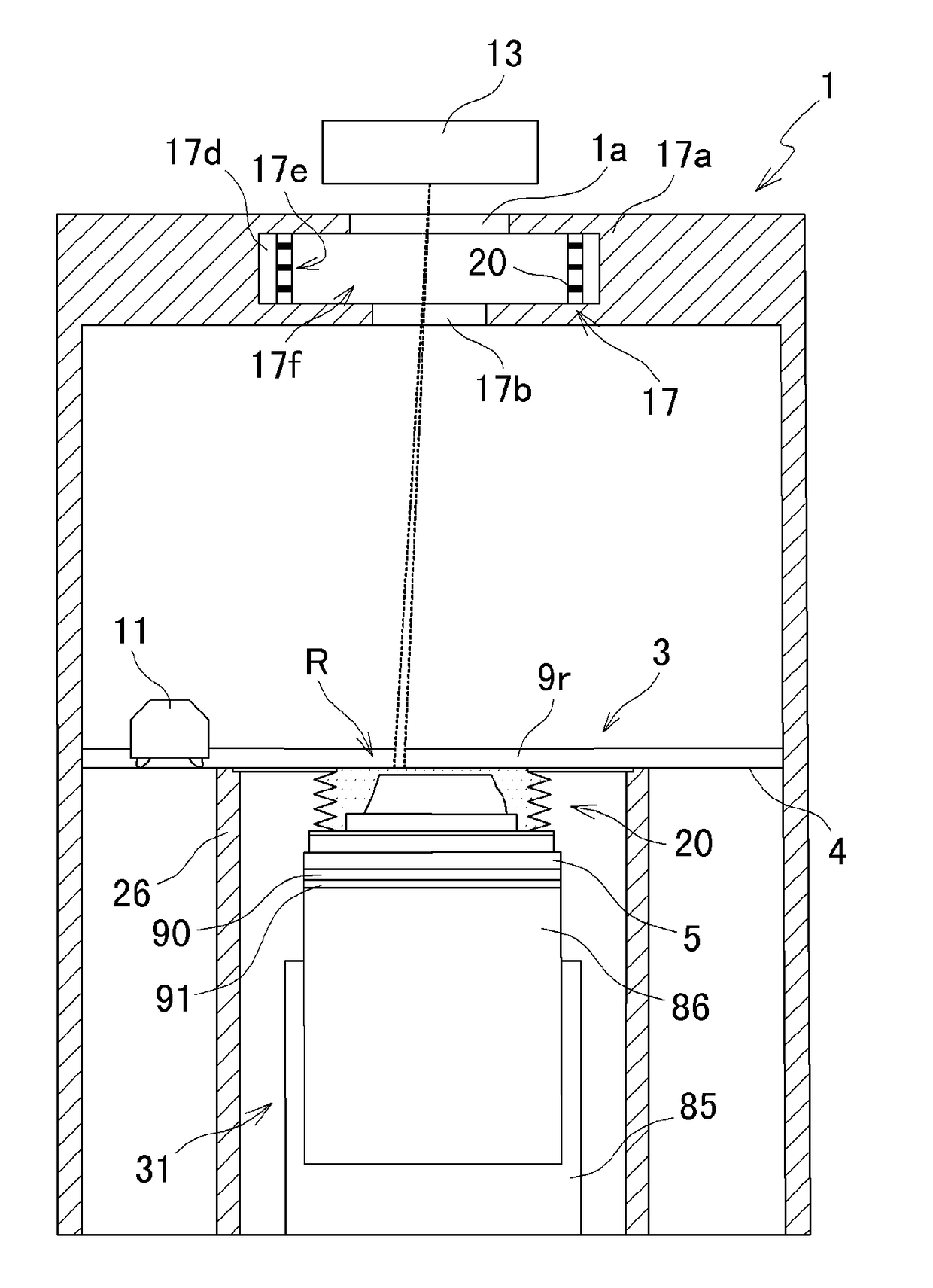
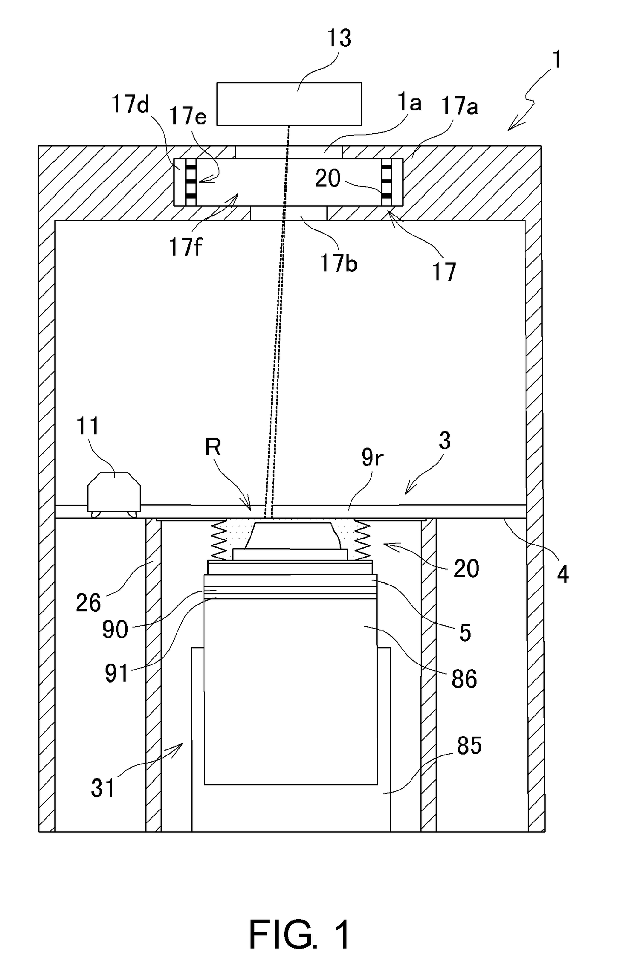
[0018]As shown in FIG. 1, a laminate molding device according to an embodiment of the present disclosure includes a molding tank 1 which covers a molding area R and into which an inert gas is filled to a predetermined concentration, a powder layer forming device 3 provided in the molding tank 1, and a laser emission unit 13 configured to emit a laser beam to a predetermined area of a powder layer and sinter material powder.

[0019]The powder layer forming device 3 includes a recoater head 11 that is movable in a horizontal uniaxial direction and elongated members 9r and 91 that are provided in a movement direction of the recoater head 11. In a space surrounded by a peripheral wall 26, a main table 5 that is movable in a vertical direction when driven by a drive mechanism 31 is provided.

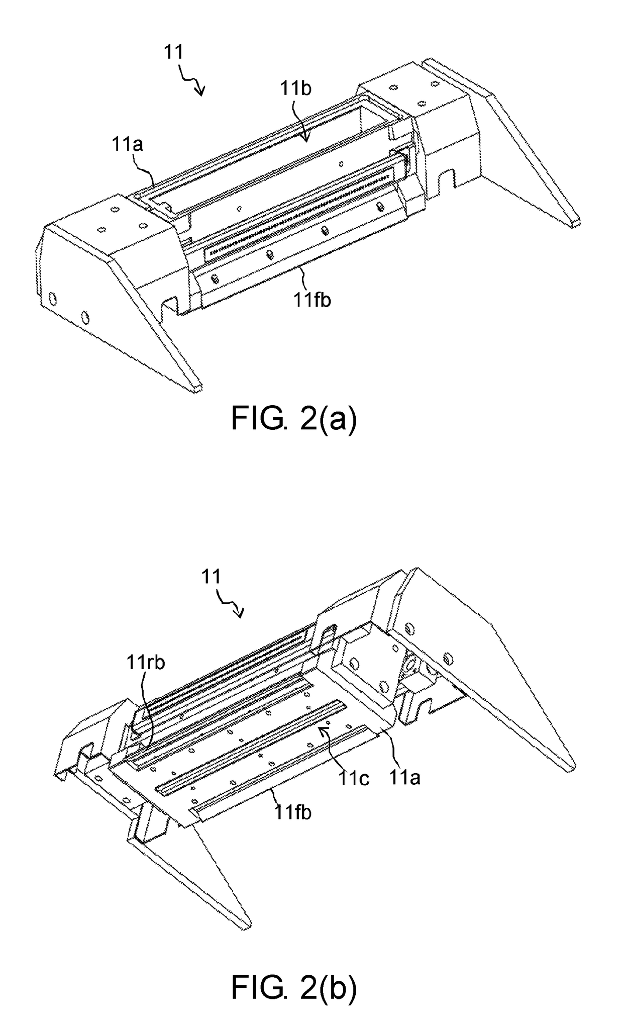
[0020]As shown in FIG. 2(a) and FIG. 2(b), the recoater head 11 includes a material accommodation unit ...


PUM

PropertyMeasurementUnit
volumeaaaaaaaaaa
temperatureaaaaaaaaaa
heataaaaaaaaaa

Abstract

A heat source isolation mechanism of the laminate molding device includes an intermediate table that is mounted on an upper surface of a main table, an auxiliary table which is provided on an upper surface of the intermediate table and of which a temperature can be adjusted, and a bellows member in which the auxiliary table is disposed and which includes a lower end that is provided on the intermediate table and an upper end that is mounted on the peripheral wall, and which expands as the main table is lowered. The bellows member is made of an insulating material. The recoater head supplies a metal material powder to a molding area inside the bellows member and a powder layer is formed on the auxiliary table, a laser emission unit emits a laser beam to a predetermined area of the powder layer and sintering is performed.

Description

CROSS-REFERENCE TO RELATED APPLICATIONS[0001]This application claims the priority benefit of Japanese application serial no. 2017-077205, filed on Apr. 9, 2017. The entirety of the above-mentioned patent application is hereby incorporated by reference herein and made a part of this specification.BACKGROUNDTechnical Field[0002]The present disclosure relates to a laminate molding device configured to mold a metal laminate molded object.Description of Related Art[0003]As a device for producing a metal laminate molded object, there is a laminate molding device described in Patent Document 1. In this laminate molding device, immediately above a molding table in a molding tank, a recoater head is moved in a horizontal uniaxial direction, a metal material powder is supplied and flattened by a material accommodation unit and a blade provided on the recoater head to form a powder layer, and a laser beam is emitted to an emission area of the powder layer by a laser emission unit to form a sin...

Claims


Application Information

Patent Timeline
Patent Type & Authority Applications(United States)
IPC IPC(8): B22F3/105B33Y30/00
CPCB22F3/1055B33Y30/00B22F2003/1056Y02P10/25B22F10/28B22F12/17B22F12/20B22F12/30
Inventor OKAZAKI, SHUJIMURANAKA, KATSUTAKA
Owner SODICK CO LTD
Learn More