Systems and methods for remediating a microannulus in a wellbore

a technology of microannulus and wellbore, which is applied in the direction of wellbore/well accessories, fluid removal, insulation, etc., can solve the problems of unfavorable fluid flow between zones, inability of fluids from one zone of geological formation to pass through the wellbore to interact with another zone, and complications in the integrity of the pressure barrier. achieve the effect of facilitating the solidification of fill material and restoring zonal isolation

Active Publication Date: 2018-10-18
SCHLUMBERGER TECH CORP
View PDF4 Cites 13 Cited by
  • Summary
  • Abstract
  • Description
  • Claims
  • Application Information

AI Technical Summary

Benefits of technology

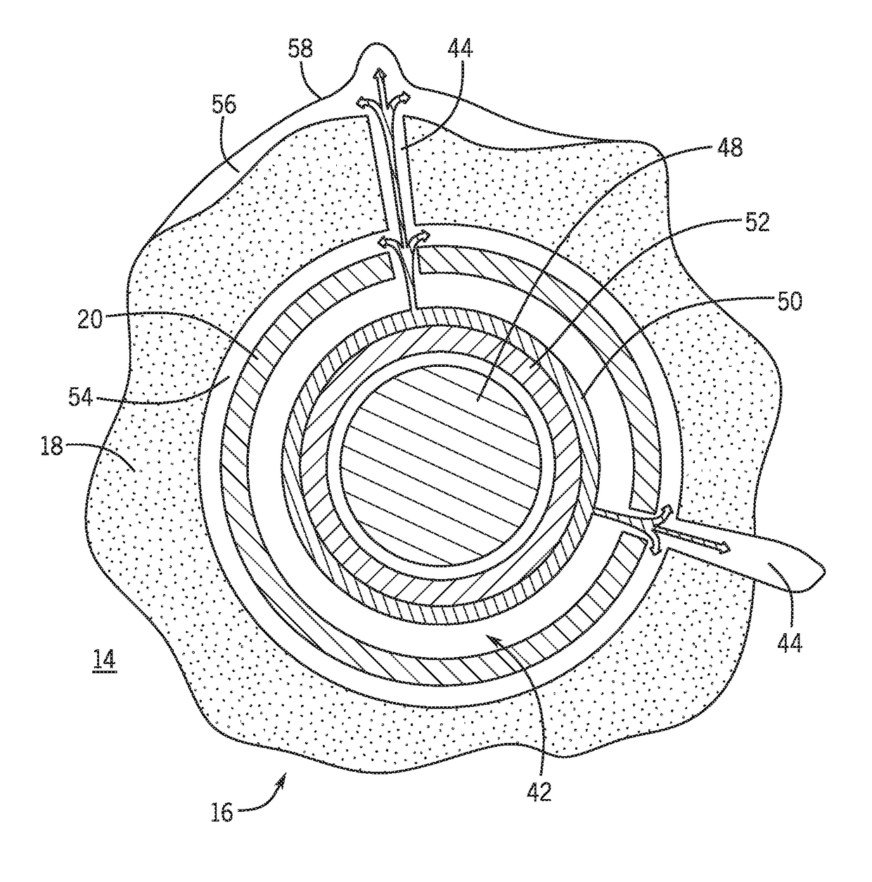
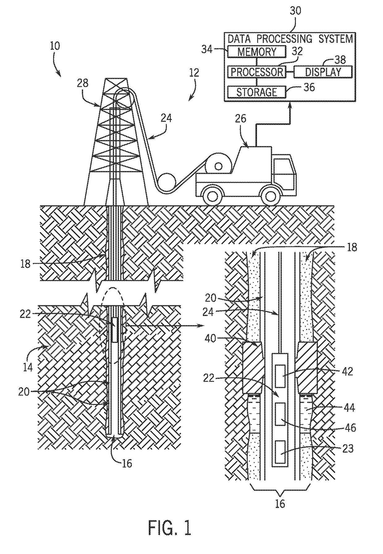
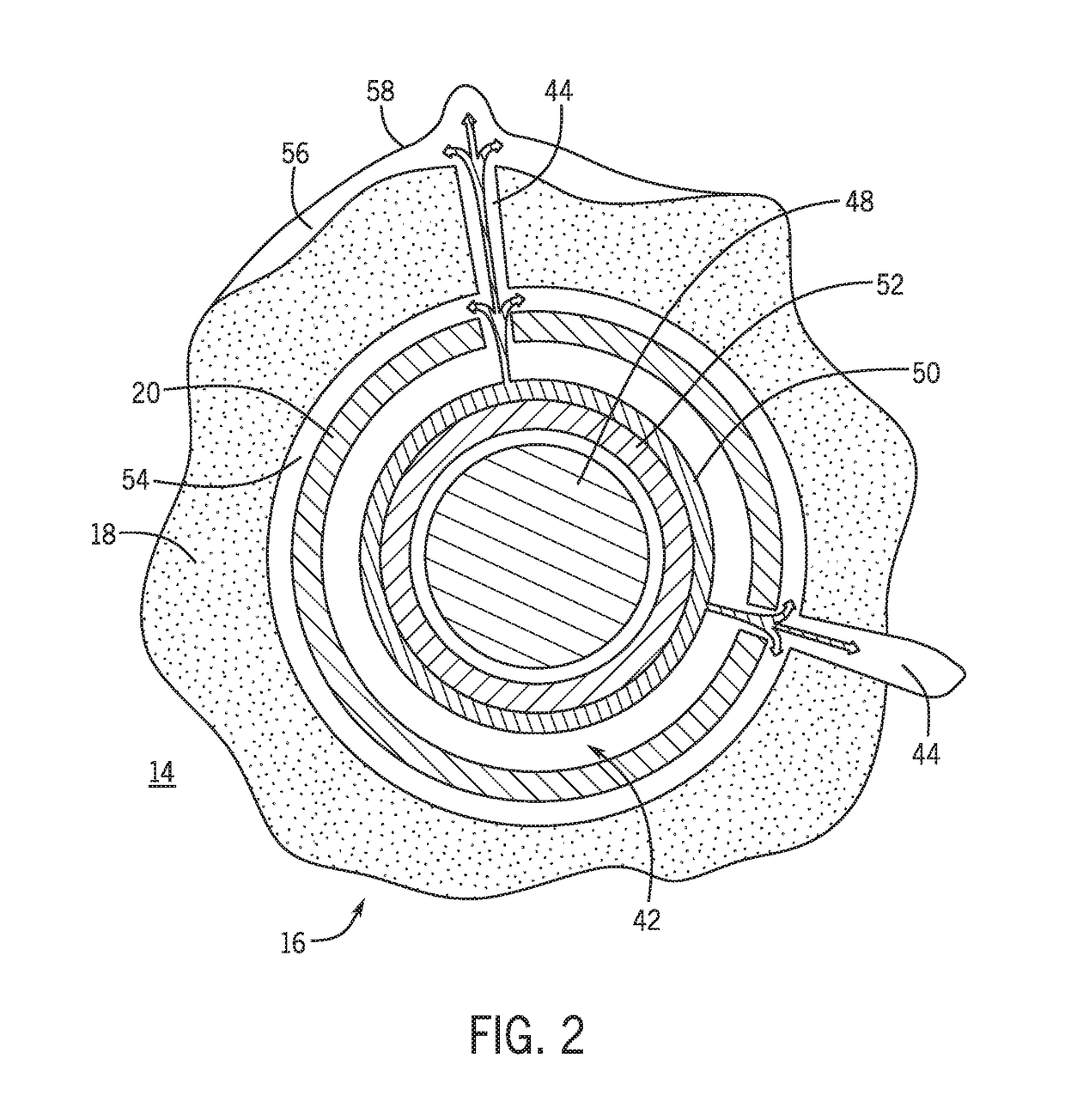
[0007]In one embodiment, a method for remediating a microannulus in a cased wellbore may include conveying a downhole tool into the cased wellbore to a location of interest. The location of interest may include one or more perforations in a casing and a microannulus. The downhole tool may include a heat generation device. The method may also include activating the heat generation device to melt a fill material at the location of interest such that the fill material flows through the perforations into one or more voids, including the microannulus, in or around cement disposed between the casing and the cased wellbore. Additionally, the method may include deactivating the heat generation device to facilitate solidification of the fill material in the one or more voids and sealing of the microannulus.
[0008]In another embodiment, a method for remediating a microannulus in a wellbore may include perforating, via a downhole tool, a casing, a cement wall, a wellbore wall, or a combination thereof to create one or more perforations into a geological formation at a location of a microannulus. The method may also include melting, via the downhole tool, an alloy adjacent to the one or more perforations such that molten alloy flows through the one or more perforations and into the microannulus. Additionally, the method may include cooling the molten alloy to solidify in place to seal the microannulus and removing excess alloy from within the casing at the location.
[0009]In another embodiment, a system for remediating a microannulus in a wellbore may include a conveyance device to convey at least a fill material and a heat generation device into a cased wellbore extending into a geological formation to a location of interest, which may include a microannulus. Additionally, the heat generation device may melt the fill material such that the fill material flows into one or more perforations in a casing of the cased wellbore at the location of interest to seal the microannulus and to at least partially restore zonal isolation.

Problems solved by technology

When the cement properly sets, fluids from one zone of the geological formation may not be able to pass through the wellbore to interact with another zone.
However, complications in the integrity of this pressure barrier may occur during the initial cementing or over time during operation of the well.
For example, pockets and / or cracks may be created within the cement that provide a means for undesirable mud / fluid flow.
Additionally, in certain circumstances, a microannulus between the cement and the casing or between the cement and the wall of the geological formation may form, possibly leading to undesirable fluid flow between zones.

Method used


Image

  • Systems and methods for remediating a microannulus in a wellbore
  • Systems and methods for remediating a microannulus in a wellbore
  • Systems and methods for remediating a microannulus in a wellbore

Examples


Embodiment Construction

[0015]One or more specific embodiments of the present disclosure will be described below. These described embodiments are examples of the presently disclosed techniques. Additionally, to provide a concise description of these embodiments, features of an actual implementation may not be described in the specification. It should be appreciated that in the development of any such actual implementation, as in any engineering or design project, numerous implementation-specific decisions may be made to achieve the developers' specific goals, such as compliance with system-related and business-related constraints, which may vary from one implementation to another. Moreover, it should be appreciated that such a development effort might be complex and time consuming, but would still be a routine undertaking of design, fabrication, and manufacture for those of ordinary skill having the benefit of this disclosure.

[0016]When introducing elements of various embodiments of the present disclosure,...


PUM


Abstract

A method for remediating a microannulus in a cased wellbore may include conveying a downhole tool into the cased wellbore to a location of interest. The location of interest may include one or more perforations in a casing and a microannulus. The downhole tool may include a heat generation device. The method may also include activating the heat generation device to melt a fill material at the location of interest such that the fill material flows through the perforations into one or more voids, including the microannulus, in or around cement disposed between the casing and the cased wellbore. Additionally, the method may include deactivating the heat generation device to facilitate solidification of the fill material in the one or more voids and sealing of the microannulus.

Description

CROSS REFERENCE TO RELATED APPLICATION[0001]This application is a Non-Provisional Application claiming priority to U.S. Provisional Patent Application No. 62 / 486,205, entitled “Method to Remediate Cement Issues with Downhole Castable Alloys,” filed Apr. 17, 2017, which is herein incorporated by reference in its entirety for all purposes.BACKGROUND[0002]This disclosure relates generally to wellbore operations, and, more specifically, to remediating cement issues in wellbore operations.[0003]This section is intended to introduce the reader to various aspects of art that may be related to various aspects of the present techniques, which are described and / or claimed below. This discussion is believed to be helpful in providing the reader with background information to facilitate a better understanding of the various aspects of the present disclosure. Accordingly, it should be understood that these statements are to be read in this light, and not as an admission of any kind.[0004]A wellb...

Claims


Application Information

Patent Timeline
Patent Type & Authority Applications(United States)
IPC IPC(8): E21B33/138E21B43/116E21B36/00
CPCE21B33/138E21B43/116E21B36/008E21B33/14E21B43/11
Inventor BILLINGHAM, MATTHEW EDWARDKALYANRAMAN, RAM SUNDER
Owner SCHLUMBERGER TECH CORP
Why Eureka
Try Eureka