Media Production Remote Control and Switching Systems, Methods, Devices, and Configurable User Interfaces
What is Al technical title?
Al technical title is built by PatSnap Al team. It summarizes the technical point description of the patent document.
a technology of remote control and media production, applied in the field of video media production, to achieve the effect of reducing latency, minimizing latency, and reducing latency network path
Inactive Publication Date: 2018-10-18
BROADCAST PIX
View PDF3 Cites 5 Cited by
Summary
Abstract
Description
Claims
Application Information
AI Technical Summary
This helps you quickly interpret patents by identifying the three key elements:
Problems solved by technology
Method used
Benefits of technology
[0006]In another implementation, a system for processing video input is provided. The system includes a media content switcher positioned at a first location and having a first connection to a public network; one or more video signal connections configured to provide one or more source video signals over the public network to the media content switcher, the one or more source video signals being from one or more cameras located at a second location remote from the first location; a control client configured to be positioned at a third location remote from the first location and the second location, the control client providing an interface to a user for controlling the selection of the one or more source video signals and the processing of the one or more source video signals with one or more media effects, the control client connected to the media content switcher over the public network; a control client server configured to communicate with the media content switcher and provide a user interface via the control client for a user to interact with the media content switcher; and a latency monitoring element, the latency monitoring element configured to monitor the latency of a plurality of network paths between the second location and the first location and to direct each of the one or more source video signals over a chosen one or more of the plurality of network paths to minimize latency of the one or more source video signals wherein the latency monitoring element includes machine executable instructions for comparing time codes and/or network path encodings associated with the one or more source video signals to determine a lower latency network path.
[0007]In yet another implementation, a system for processing video input. The system includes a media content switcher positioned at a first location and having a first connection to a public network; one or more video signal connections configured to provide one or more source video signals over the public network to the media content switcher, the one or more source video signals being from one or more cameras located at a second location remote from the first location; a control clie
Problems solved by technology
Some recent systems have allowed a limited selection of source devices to be located remotely or for a partial cont
Method used
Image
Click on the blue label to locate the original text in one second.
Reading with bidirectional positioning of images and text.
Examples
example ways
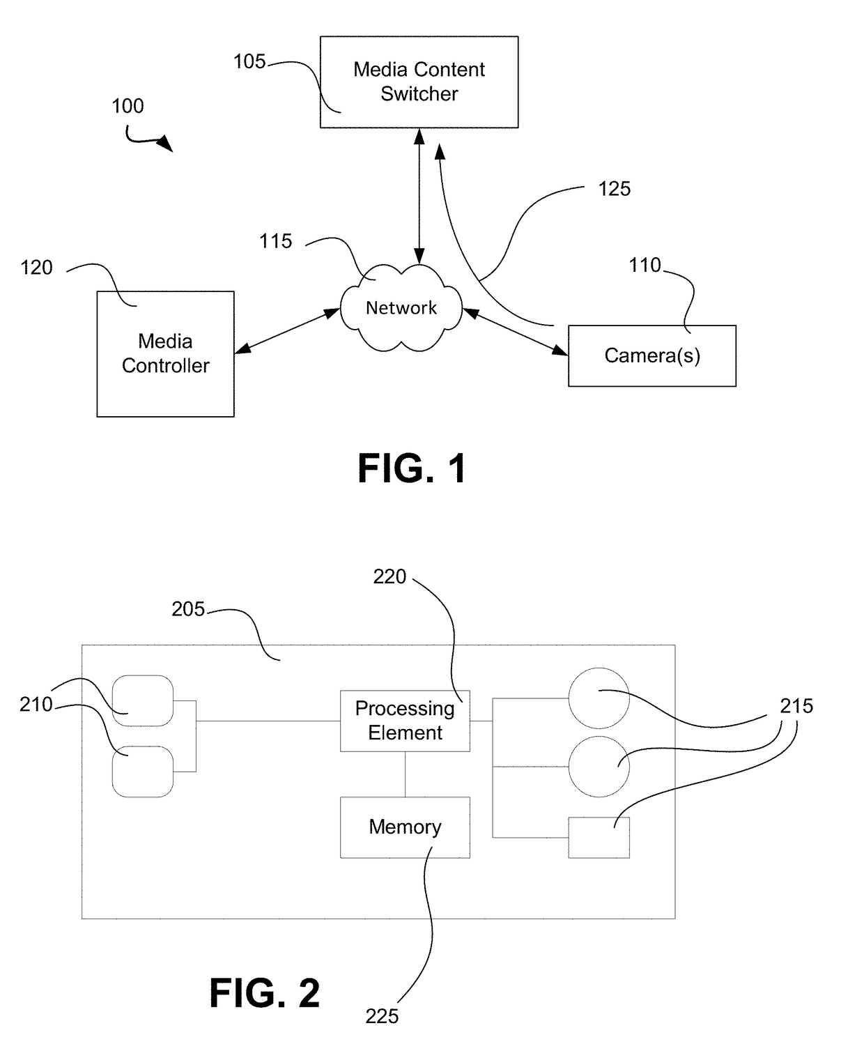
[0064 of determining latency include, but are not limited to, using a time stamp on media content signals as they are communicated from one or more cameras to a component of a media content switcher, sending a separate signal from a media content signal from a location of the one or more cameras to a location of a medic content switcher to determine time of transmission, sending a separate signal from a media content signal from a location of a media content switcher to a location of one or more cameras to determine time of transmission, and any combinations thereof.
[0065]In one example, a latency monitoring element is part of a local media signal control device. In one such example, a local media signal control device includes a connection to one or more cameras at the location, a connection to a public network, a processor, appropriate circuitry, and / or machine executable instructions for checking latency of a connection and selecting a proper network path.
[0066]In another example...
PUM
Abstract
A system for processing video input having a media content switcher at one location, one or more video signal sources at a second location, and a control client at a third location. The control client is connected to the media content switcher via a public network and providing an interface to a user for controlling the selection of one or more video signals from the sources and the processing of the one or more signals with one or more media effects. A latency monitoring element may provide monitoring of latency of different network paths of the public network and direct video signals over one or more chosen paths to minimize latency of the source signals.
Description
RELATED APPLICATIONS[0001]This application claims the benefit of priority of U.S. Provisional Patent Application Ser. No. 62 / 486,447, filed on Apr. 17, 2017, and titled “Media Production Remote Control and Switching Systems, Methods, Devices, and Configurable User Interfaces,” which is incorporated by reference herein in its entirety.FIELD OF INVENTION[0002]The present invention generally relates to the field of video media production. In particular, the present invention is directed to media production remote control and switching systems, methods, devices, and configurable user interfaces.BACKGROUND[0003]Video media production occurs across multiple fields including broadcast, cable, Internet, and satellite programming (e.g., news, commercials, entertainment programming, documentaries, reality shows, music videos, etc.); corporate programming (e.g., events, meetings, conventions, employee educational programming, etc.); product video (e.g., how-to-use, promotional, etc.); educatio...
Claims
Application Information
Patent Timeline
Application Date:The date an application was filed.
Publication Date:The date a patent or application was officially published.
First Publication Date:The earliest publication date of a patent with the same application number.
Issue Date:Publication date of the patent grant document.
PCT Entry Date:The Entry date of PCT National Phase.
Estimated Expiry Date:The statutory expiry date of a patent right according to the Patent Law, and it is the longest term of protection that the patent right can achieve without the termination of the patent right due to other reasons(Term extension factor has been taken into account ).
Invalid Date:Actual expiry date is based on effective date or publication date of legal transaction data of invalid patent.